


RINSE TANK HEATER SYSTEM
FUNCTION
The Rinse Tank Heater System is electrically connected in the circuit so that it is dependent upon the
dishwasher being properly filled with and maintaining a safe water level. The automatic fill system, therefore, should
operate properly before the heat system can be engaged. The circuit is controlled by a heat switch (mounted on the
front control panel), a thermostat (mounted behind the lower front panel), a water level control (mounted in the
control box), and a heater relay (mounted in the control box), with the coil being activated by the thermostat.
INDICATORS OF POSSIBLE MALFUNCTION
Once the machine, has been properly filled and the heat system engaged, the heat circuit should operate by
merely turning on the heat switch. Should the rinse tank heat, be it either too high, too low, or no indication of
temperature at all, the following checkouts should be made.
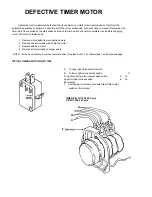
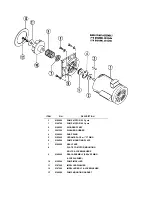
CHECKOUT OF HEATER SYSTEM FOR RINSE TANK (Refer to drawing, figure 1)
NOTE: THE FOLLOWING CHECKOUTS SHOULD BE DONE BY A QUALIFIED SERVICE PERSON OR
ELECTRICIAN.
1. If temperature is too high: adjust thermostat, using thermostat instructions in this manual.
2. If temperature is too low, adjust thermostat as above, then:
a. Turn off power to machine by tripping customer circuit breaker to "off" position.
Turn off machine circuit breaker located on right side of control box.
b. Remove lower cover plate on control box (held by single screw).
c. Make sure rinse temperature is below 180° (preferably about 140°).
d. Reapply power. Turn on master switch and observe heat relay (4 pole mounted lower left inside control
box) while heat switch is turned "on" and "off". If relay contacts move in and out, see instructions under
"B"; if not, proceed with "A".
A. If heat relay does not close:
1. There is an insulated movable bar on the relay across the top of the four contacts. With insulated
probe, depress this bar and observe the rinse thermometer; the temperature should rise noticeably
in a minute or two. If it moves very slowly, it would indicate that one or more elements are faulty. If it
moves constantly higher at a good rate, elements are okay.
NOTE: A check with an amp probe at position E, if available, can be made. Each row of elements should draw 30
amps with a total approximate amperage draw of 60 amps for both rows of elements. (Single phase). Replace any
defective elements.
A. 2. With master and heat switches on:
a. Check position 1, figure 1. Voltage should be 220V; if not, checkout heat
switch and replace if necessary.
b. Check position 2; there should be no voltage.
If there is, readjust thermostat per thermostat adjustment instructions.
c. Check position 3; voltage should be approximately 120V to ground. d. If voltage being applied
on positions 1, 2. and 3 check out okay. then the relay should be replaced. Coil is probably defective.
16
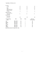
Содержание 100 B/PRB
Страница 6: ......
Страница 26: ......
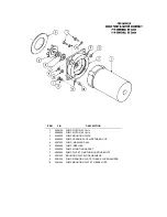
Страница 46: ...45 BOOSTER TANK HEATER ELEMENT P N 0060500 WASH TANK HEATER ELEMENT P N 0058000...