


TIMER FOR MODEL 100 DISHWASHERS
General Description
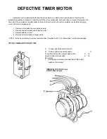
The timer is a self-contained (frame-mounted) timer of the repeating cycle type. It is mounted on
the control panel of Jackson Automatic Dishwashing machines, to control the automatic functions of
these machines. It consists of a clock motor which operates on
60 cycle AC, 220 VAC. In addition to the
clock motor, the timer also contains a driven cam arrangement which operates three micro switches.
Principle of Operation
The timer controls various operations of the automatic washers as per wiring diagram for each
machine, however, the timing cycle and the micro switches are the same for each model. The time for
ONE COMPLETE REVOLUTION of the cam shaft is approximately 120 seconds, allowing two wash
and two rinse operations for each complete revolution of the cam shaft. The micro switch nearest the
timer motor is the hold circuit and uses both the NO and NC contacts. The middle micro switch controls
the wash and uses the NO contact. The micro switch farthest away from the timer motor controls the
rinse and uses just the NC contact.
Service Instructions
CAUTION: ALWAYS REMOVE THE POWER TO THE MACHINE BEFORE WORKING ON THE
CONTROL PANEL OR WHILE SERVICING THE COMPONENTS ON THE SWITCH
PANEL. ALL ELECTRICAL CHECKS SHOULD BE MADE BY QUALI-FIED PERSONNEL.
Timer operation can be observed after removing the control panel from the control box by
loosening the four screws holding it. Hang the control panel using the two right hand screws with the
back side of the panel outward.
If it is determined that the timer is defective, it is recommended that a new timer be in-
stalled. However, limited field maintenance can be accomplished as follows:
A frozen contact on a micro switch will be indicated by one function being executed all the time or
the absence of a click when the switch arm is actuated. The micro switch
is replaced by:
1. Remove all wires from the timer, properly tag them to assure proper replacement.
2. Remove the two screws which hold the timer to the control panel.
3. One screw holds the micro switches, cams and actuating arms in the frame. This screw
is seen on the side opposite the motor. Remove this screw. NOTE: Be sure to note which
cam goes with which micro switch. Cam nearest timer motor has % raised, cam center,
larger depressed areas, cam farthest from timer motor, smallest depressed areas.
4. The unit can now be taken apart and the defective micro switch replaced.
5. Reassemble. NOTE: The flanges on the cams are such that they only mesh in one
direction. The shorter flange on the cams always points toward the drive motor.
The timers cam drive system is equipped with a clutch to enable one to view the operations of the
cams and micro switches. Remove power to machine BEFORE touching timer. Rotate
cams by turning
with fingers; cams will turn in one direction only. Do not force them. As cams actuate switches, listen
for the click of the switch or test the switches with an ohmmeter.
10
Содержание 100 B/PRB
Страница 6: ......
Страница 26: ......
Страница 46: ...45 BOOSTER TANK HEATER ELEMENT P N 0060500 WASH TANK HEATER ELEMENT P N 0058000...