69
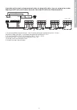
9. Aansluitschema MX in netwerk met modemcommunicatie, Schéma de câblage du MX installé en réseau avec communication par modem,
Wiring diagram for MX in netwerk with modem communication, Stromlaufplan MX in Netzwerk mit Modemkommunikation
A = Communicatie mogelijkheid via telefoonlijn/modem (9 pin - 25 pin), Communication possible par ligne télephonique/modem (9 broches - 25 broches),
Communication via telephone/ modem [9pins - 25 pins], Kommunikationsmöglichkeit über Telefon/Modem (9-Pin - 25-Pin)
B = Communicatie mogelijkheid via PC (9 pin - 9 pin), Communication possible par PC (9 broches - 9 broches),
Communication with PC [9 pins - 25 pins], Kommunikationsmöglichkeit über PC (9-Pin - 9-Pin)
C = Afscherming, Écran de protection, Shielding, Abschirmung
D = Twistedpair, Paire torsadée, Twisted pair, Twistedpair
D
maximum 31 MXs
1
2
3
31
GRD A
B
RS
A
RS
B
RS
A
RS
B
GND
U3
RS
A
RS
B
RS
A
RS
B
GND
U3
RS
A
RS
B
RS
A
RS
B
GND
U3
RS
A
RS
B
RS
A
RS
B
GND
U3
C
R=120 Ohm
MI 31
RS485
NO NC COM NO NC COM N
L
supply
RY2
RY 1
SUB D9 - female
B
A
com-poort
PC
modem
"Hayes compatible"
Bijlagen,
Anne
x
es,
Appendices,
Anlagen


