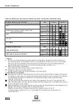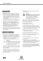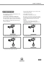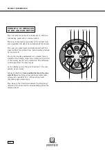
I N I T I A L O P E R AT I O N
Page 22
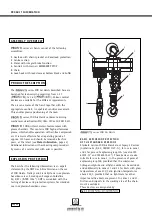
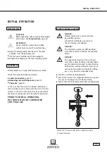
Control valve (on motor)
Note: In order to connect the hoses to the control
valve, we recommend removal of the hose adapter.
Remove the hose adapter (secured via central bolt).
Attach the hoses to the corresponding nipples
(see designation in illustration)
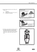
Secure the hoses using the one-ear hose clamps and
crimping tool.
Secure the strain-relief rope.
AT T E N T I O N !
The strain-relief rope must be installed with
the correct length, in order to prevent loading
of the hoses.
Pull the bellows over the hose adapter.
The upper collar of the bellows fits into the recess of
the hose adapter.
In order to secure the hose adapter to the control
valve, a long A/F 6 socket spanner must be guided
between the three hoses, through the middle of
the bellows and inserted into the hexagon socket of
the bolt.
F - CO N T R O L C O N N E C T I O N
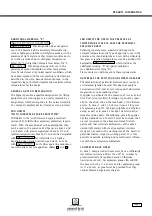
Pull the bellows over the hose bundle for F-control. For
F-control for lifting and lowering only, remove approx.
80 mm of hose bundle protective sheathing; for F-con-
trols with additional functions (trolley/crane movement)
remove approx. 160 mm from end of protective sheathing.
Pull the strain-relief ropes through the eye bolt
and secure using rope clamps.
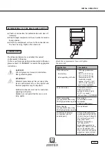
Insert the control hoses:
See illustration above
Compressed air
with hose designation 1 or colour: white
Movement direction "lift"
hose designation 2 or colour: green
Movement direction "lower"
hose designation 3 or colour: red
Bellows with A/F 6 socket spanner
Hose adapter with nipples designation lift, lower
Dowel pin
Raise
Compressed air
connection
Lower
Содержание PROFI 10 Ti
Страница 1: ...J D N O P E R A T I O N M A N U A L A I R H O I S T S 16 10 6 3...
Страница 58: ...NOTES Page 58...

