


23
This header adopts Intel’s PC/PCI technology to deliver Sound Blaster 16 compatibility to PCI Bus
sound card, enabling users to play real-mode DOS games. Connect the cable provided by PCI
sound card to this connector.
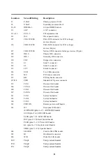
Signal of SB-LINK header
Pin 1
GNT#
Pin 2
Ground
Pin 3
Key
Pin 4
REQ#
Pin 5
Ground
Pin 6
SIRQ
2.3.16 Infrared connector (IR)
Serial Port 2 can be configured to support an IrDA module connected to this connector. After the
IrDA interface is configured, data can be transferred between devices by using application
software.
Signal of IR connector
Pin 1
VCC
Pin 5
IRTX
Pin 2
FIRRX
Pin 6
NC
Pin 3
IRRX
Pin 7
CIRRX ( for W83977CTF only )
Pin 4
Ground
2.3.17 WOL header (WOL)
This header is used to implement the Wake on LAN feature. Connect this header to a network
interface card (NIC) that supports the Wake on LAN technology. The NIC monitors network traffic.
When it detects a Magic Packet, it asserts a signal through the WOL header to wake up the
computer. This signal can wake up the computer only when the power cord is still plugged into the
socket and the computer is turned off.
Signal of WOL header
Pin 1
5VSB
Pin 2
Ground
Pin 3
LID_ON
2.3.18 Clear CMOS jumper block (CLRTC)
To reset the RTC (Real Time Clock) CMOS data, you need to change the jumper cap of JP1
from 1-2 close to 2-3 close, then set to 1-2 close again. After that, you should get into BIOS
setup program and choose LOAD SETUP DEFAULTS, then you will now get original
manufacturer default setting in your CMOS.
2.3.19 Keyboard-Power-On Enable/Disable jumper block (KB ON)
The motherboard supports a Keyboard-Power-On feature. The system can be powered on by
pressing a set of user-defined-key simultaneously. The default setting, 2-3, makes this feature
enabled. If you want to disable the Keyboard-Power-On feature, put the jumper cap to pins 1-2.


