


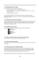


17
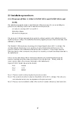
2.3 Installation procedures
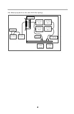
2.3.1 Processors (P.Slot 2, S.Slot 2, FAN1/FAN1A and FAN2/FAN2A and
FAN3)
The motherboard supports single or dual Pentium ® II Xeon processor. If you are installing two
processors, the following values must be identical for both processors:
L2 cache size and type (ECC or non-ECC)
Operating voltages
Bus and core frequencies
The processor’s VID pins automatically program the voltage regulator on the motherboard to the
required processor voltage. The motherboard currently supports processors that run internally from
400 MHz to 500 MHz.
The Pentium ® II Xeon processor is packaged in a Single Edged Contact (S.E.C.) cartridge. The
cartridge includes the processor core, second-level cache, thermal plate and back cover. The
processor connects to the motherboard through the Slot 2 connector, a 330-pin edge connector.
When mounted in a Slot 2 connector, the processor is secured by a retention mechanism attached to
the motherboard.
First, screw the main body of Slot 2 retention mechanism to the motherboard then insert the
processor cartridge along the retention mechanism in vertical direction. Finally, attach the
cooler’s power cable to the processor fan header on the motherboard.
Signal of FAN1/2 header (processor fan header)
Pin 1
Ground
Pin 2
+12 V
Pin 3
SENSE
Note 1. Processor cooler is always required to prevent over-heat.
Note 2. The second-level cache is located on the substrate of the S.E.C. cartridge. The cache size
and cacheable memory size are dependent on the processor used.
Note 3. Processor can be installed in either of the two Slot 2 sockets without any order restriction.


