Explanation:
The system default control instruction is the PC CONTROL state. When the system is
closed or the POWER is switched, the system will be automatically set to POWER SELF state.
2. Methods 2
POWER ON/OFF Set POWER Control Set
Fig 4-10-2 Selecting Control Instruction
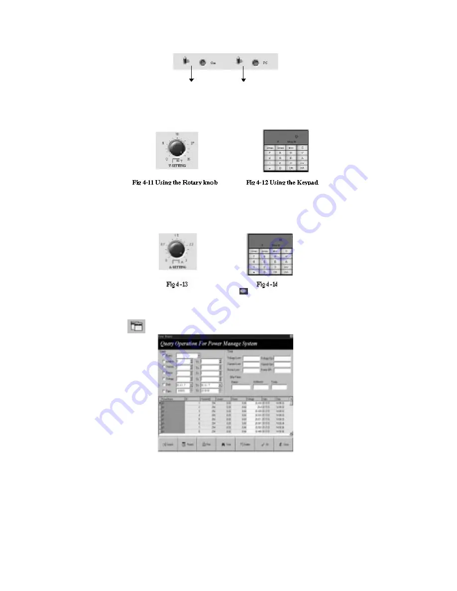
4.7 Set the Voltage Range
There are two methods to set the voltage range: one is by using the rotary button and the other is by using
the keypad (0.004~36.000). If you want to set accurately, use the keypad.
1. Using the rotary knob: Move the mouse to the icon and then rotate the knob.
2. Using the keypad: Select the “V” button, enter the data and then select the “ENTER” button.
4.8 Set the Max Current
There are two methods to set the voltage range: one is by using the rotary knob and the other is by using
the keypad. If you want to set accurately, use the keypad. In general, you can use the rotary knob.
1. Using the rotary knob: Move the mouse to the icon
and then rotate the knob.
2. Using the keypad: Select the “A” button, enter the data and then select the “ENTER” button.
4.9 Query the Report
Select the button
and the diagram as shown in Fig. 4-15 will be displayed.
Fig 4-15 Query the Report
1. Set the Query Conditions: Set the parameters in the “Query” frame.
2. Query: After setting the conditions, select the “SEARCH” button and all the records compatible
with the conditions will be listed.
3. Set the Report: Select the “.
4. Print the Report: Select “PRINT”.
5. Query Totally: Select “TOTAL”. The data range must be selected and the other conditions cannot
be selected. Its main function is to analyze POWER so as to list the POWER that will overflow the
most data. The overflowing data includes the voltage overflow, the current overflow and the power
overflow.
6. Delete the History Record: Select “DELETE” and the diagram as shown in Fig. 4-24 will be
displayed. If you confirm to delete, select “YES”.


