iSYSTEM, March 2017
16/66
Trace Line Calibration
Majority of the modern embedded microcontrollers providing trace functionality, implements a so called
message based trace port, where an individual trace message is broadcasted off the microcontroller through a
relatively narrow physical trace port in multiple CPU cycles, at frequencies, which can be well over 100 MHz.
Typically, the trace port is combined from trace data lines and a trace clock line, which is used to sample trace
data lines on rising, falling or both edges (depending on the individual implementation).
At lower frequencies and good signal integrity we can consider the clock and data lines as pure digital signals,
which are correctly phase aligned. As such, the external trace tool can capture them accurately without any
problems.
Nowadays, capturing of the valid trace data becomes more and more challenging due to the various signal
integrity issues (noise, skew, crosstalk, reflections, ground bounce…), which are introduced either due to the
high frequency trace clock & data, due to the bad target PCB design or a combination of both. THE IC5500 has
the ability to compensate for these issues via Trace Line Calibration functionality, which allows shifting
threshold voltage and clock phase at the capture time of the trace data. When Trace Line Calibration is
performed, it auto scans over these two dimensions and searches for valid and invalid settings and finds an
optimum data eye.
Example
Let’s assume we have a Cortex-M3 based NXP LPC1768 microcontroller running at 95 MHz. At this frequency,
some of the signal integrity issues will show up for sure. After the debug download, the application should be
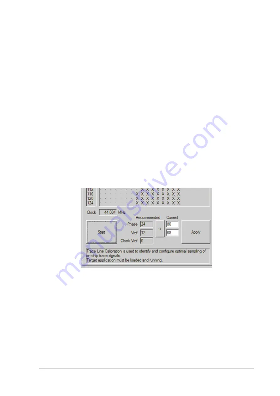
run. Next, the “Start” button in the “Hardware/Tools/ Trace Line Calibration” should be pressed, which starts the
auto-scan. After a couple of seconds, the result of the scan is collected and recommended “Vref” and “Phase“
values are provided. Typically, the user just needs to press the “->” button to use the recommended values (or, if
desired, enter them manually) and finally use the Apply button.
Configuration part of the Trace Line Calibration dialog
Newly applied values are stored upon Save Workspace and also used on the next debug download.
The following picture shows the result of the Trace Line Calibration and the corresponding timing view of
signals on the trace port.


