background image

June 2011: Revision 002


25 


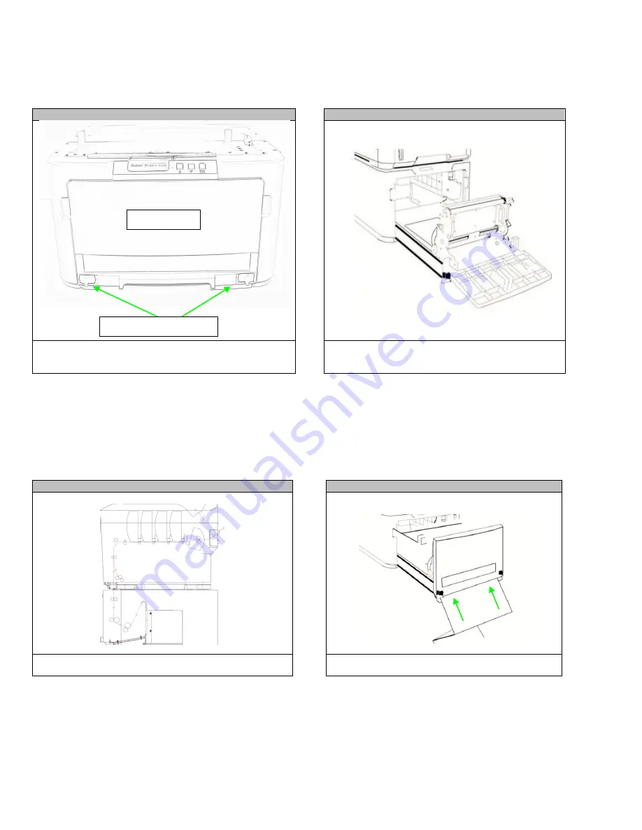
Media Set Up: Loading Paper into the Feeder, Option 2 


STEP 1 


STEP 2 


Push the guide tray latches inward and pull the guide tray 
forward about 12 inches.  


Push the guide tray latches inward and pull the guide 
tray forward. Open the guide door, load door and 
guide channels.   


STEP 3 


STEP 4 


Front loading paper path is pictured above.  


Insert paper in the front bottom loading slot until it 
goes into the paper tray.  


Guide Door 

Guide Tray Latches 

Содержание iTerra Elite ll

Страница 1: ...iTerra Elite ll User Guide ...

Страница 2: ...rator 15 8 Menus 16 Printer Configuration Menu 16 Print Information Menu 17 Printer Shutdown Menu 17 9 Major Printer Components and Paper Path 18 10 Feeder Part Names 19 11 Loading Media 20 Loading Cut Sheet Paper into the Printer Tray 20 Media Set Up Loading Paper into the Feeder Option 1 22 Media Set Up Loading Paper into the Feeder Option 2 25 12 Paper Sensor Error Codes 28 Clearing Paper Jams ...

Страница 3: ...Group Inc and that such voluntary risk allocation represents a fundamental part of the agreement reached between The Imaging Systems Group Inc with the purchaser The Imaging Systems Group Inc shall not be liable for any special direct or indirect incidental consequential exemplary punitive or any similar or other damages of any nature suffered by the purchaser whatsoever including without limitati...

Страница 4: ...accompanied by an RMA number obtained by calling the iSys Service Department at 403 204 5200 or as otherwise instructed Shipping and handling charges to vendor for repair are the sole responsibility of the customer iSys will cover shipping charges on the return of the repaired unit for the term of the warranty as stated above Shipping will consist of Standard Shipment level or Best Effort Accelera...

Страница 5: ...s into a grounded outlet If the plug does not fit the outlet may be an older non grounded type Contact an electrician to have the outlet replaced Do not use an adapter to defeat the grounding Install the product near an easily accessible power outlet Avoid damaging the power cord Do not put anything on it or place it where it will be walked on If the cord becomes damaged or frayed replace it immed...

Страница 6: ...June 2011 Revision 002 6 ...

Страница 7: ...June 2011 Revision 002 7 ...

Страница 8: ...h two people lift the top feeder box off of the bottom printer box Open the feeder box Remove the feeder STEP 3 STEP 4 Remove the wing nut on the bottom of the feeder before placing upright on any surface Position the feeder at the back of the cart as shown Back of cart Wing Nut ...

Страница 9: ...ose the feeder door Lift the lid off of the printer box STEP 7 STEP 8 With two people remove the printer from the box and remove the packaging tape as shown Press button to open lid STEP 9 STEP 10 Remove fuser shipping lock Pull the drums toners out of the printer Internal packing material ...

Страница 10: ...all four toners into the four drums STEP 14 Keep the printer level while lowering it onto the feeder ensure you are aligning the printer with the pins located on the top of the feeder STEP 15 When the iTerra Elite II is fully assembled the printer should look like the image above STEP 13 Remove the letter tray shipping lock ...

Страница 11: ...f 80g m paper 4 Multi purpose tray Used for feeding heavier paper stocks envelopes and other special media Also for manual feeding of single sheets when required 5 Paper level indicator 6 Front cover release lever 7 Multi purpose tray release recess 8 Top cover release button 9 LED heads 10 Fuser release levers 11 Toner cartridges C M Y K 12 ID units C M Y K 13 Duplex unit when fitted The display ...

Страница 12: ...FF switch 2 AC power socket 3 Duplex unit when fitted 4 Rear face up stacker 5 USB interface 6 ACC interface host USB 7 Network interface 8 Parallel interface The Network Interface may have a protective plug which must be removed before connection can be made This view shows the connection panel the rear output stacker and the location of the optional duplex two sided printing unit ...

Страница 13: ...ess the Enter button on the control panel to enter the menu 2 Press the Menu down button and scroll to the Shutdown menu 3 Press the Enter button 4 Press the Enter button to continue 5 Press the Enter button to execute 6 At the prompt turn the power switch OFF ...

Страница 14: ...conds or longer to jump from top to bottom 8 Enter Button In the ONLINE or OFFLINE mode enters the Menu mode In the Menu mode determines the setting selected 4 On Line Button Switches between ONLINE and OFFLINE Scrolls the HELP screen Forced printing on the paper currently loaded when pressed with WONG PAPER or WRONG PAPER SIZE displayed 9 Cancel Button Deletes the data being printed or received w...

Страница 15: ... display the setting An asterisk will appear next to the setting indicating that this setting is currently in effect 5 Do one of the following Press Back again to move up to the list of menus or Press On Line or Cancel to exit from the menu system and return to standby How to Change the Settings Administrator You can set whether to ENABLE or DISABLE each category in the user menu Disabled categori...

Страница 16: ...eb Remote version IPv6 Address Local IPv6 Address Global Remote version Displays the full printer name Displays an abbreviated version Displays the IPv4 Address of the network Displays the Gateway Address of the network Displays the Mac Address of the printer Displays the Network firmware revision Displays the Web remote version Displays the IPv6 Address Local of the network Displays the IPv6 Addr...

Страница 17: ...ll down to this parameter and select execute to print out a PCL font list IBM PPR Font List Execute Scroll down to this parameter and select execute to print out an IBM PPR font list EPSON FX Font List Execute Scroll down to this parameter and select execute to print out an Epson FX emulation font list Usage Report Execute Scroll down to this parameter and select execute to print out a list of col...

Страница 18: ...002 18 9 Major Printer Components and Paper Path 7 1 Paper Exit 2 Fuser Unit 3 Top Cover 4 Printer Operator Panel 5 Front Cover 6 Cut Sheet Paper Tray 7 Feeder Operator Panel 8 Fan Fold Paper Tray 9 Feeder 4 5 3 2 1 6 8 9 ...

Страница 19: ...June 2011 Revision 002 19 10 Feeder Part Names Guide Funnel Paper Tray Feed Rollers Guide Channels Load Door Latches Load Door Guide Door Loading Slot Guide Tray Latches Guide Tray ...

Страница 20: ...P 3 Load paper letter headed paper face down and top edge towards the front of the printer as shown Adjust the rear stopper a and paper guides b to the size of paper being used iTerra Elite II IMPORTANT Set paper size dial to the size of paper being used To prevent paper jams Do not leave space between the paper and the guides and rear stopper Do not overfill the paper tray Capacity depends on the...

Страница 21: ...m the top of the printer Stacking capacity is approximately 350 sheets for the Elite II depending on paper weight For face up printing make sure the face up rear stacker a is open and the paper support b is extended Paper is stacked in reverse order Capacity is approximately 100 sheets of 20 lb US Bond 75 g m2 paper CAUTION Do not open or close the rear paper exit while printing as it may result i...

Страница 22: ...door load door and guide channels STEP 3 STEP 4 Place the paper in the tray with the Tick Mark facing up and on the right to the front of the feeder Lift the tension roller up and slide the paper between both rollers NOTE Please ensure the rear face up stacker is open before printing fanfold paper Guide Door Guide Tray Latches Guide Door Load Door Tick Mark Front of Feeder Tension Rollers ...

Страница 23: ...he width of the guide if necessary Turn the Knob COUNTERCLOCKWISE to NARROW the guide Turn the Knob CLOCKWISE to WIDEN the guide Ensure there is no space between the Guide Channels and the paper too wide Ensure the paper is not compressed between the Guide Channels too narrow Raise the paper between the guide channels until it is lightly touching the feed rollers Media Guide Channels ...

Страница 24: ... is aligned straight Close the guide channels and the load door STEP 11 STEP 12 Close the guide door Slide in the guide tray ensure the tray is fully latched When the Require Load message appears press the Load button The message STATUS IDLE should be displayed on the feeder operator panel you are ready to print ...

Страница 25: ...nd pull the guide tray forward about 12 inches Push the guide tray latches inward and pull the guide tray forward Open the guide door load door and guide channels STEP 3 STEP 4 Front loading paper path is pictured above Insert paper in the front bottom loading slot until it goes into the paper tray Guide Door Guide Tray Latches ...

Страница 26: ...o change the width of the guide if necessary Turn the Knob COUNTERCLOCKWISE to NARROW the guide Turn the Knob CLOCKWISE to WIDEN the guide Ensure there is no space between the Guide Channels and the paper too wide Ensure the paper is not compressed between the Guide Channels too narrow Raise the paper between the guide channels until it is lightly touching the feed rollers Tension Rollers Media Gu...

Страница 27: ... is aligned straight Close the guide channels and the load door STEP 11 STEP 12 Close the Guide Door Slide in the Guide Tray ensure the tray is fully latched When the Require Load message appears press the LOAD button The message Status Idle should be displayed on the feeder operator panel you are ready to print ...

Страница 28: ... Door Tray Push Guide Tray Completely into the Feeder Ensure Guide Tray Latches are Locked Msg Funnel Full Remove all Paper from the Guide Ensure No Paper Remains in the Guide Funnel Reload Fanfold Paper Manually Msg Path Full Remove all Paper from the Guide Ensure No Paper Remains in the Guide Funnel Reload Fanfold Paper Manually Please refer to the error list below in the event you receive an er...

Страница 29: ... not positioned between load sensors properly after load advance Status Error 31 Cutter did not leave home position in required time Status Error 32 Cutter did not finish cut in required time or can t home it Clearing Paper Jams STEP 1 STEP 2 Press the cover release and open the top cover Note the position of the four toners cartridges a and image drums b It is essential that they go back in the s...

Страница 30: ...b belt c fuser or d fuser pressure release lever To remove sheet from the front lift the sheet from the belt and pull it forward into the internal drum cavity to withdraw the sheet CAUTION The green image drum surface at the base of the Image Drum is very delicate and light sensitive Do not touch it and do not expose it to normal room light for more than 5 minutes If the drum unit needs to be out ...

Страница 31: ... To remove a sheet in the fuser push the two retaining levers e towards the rear of the printer t0 release the fuser Withdraw the fuser unit using the handle f STEP 9 Press release lever g and pull trapped paper from the fuser NOTE If the sheet is well advanced into the fuser only a short length is still visible do not attempt to pull it back ...

Страница 32: ...in the correct order STEP 12 Open the rear exit tray h and check for sheets of paper in the rear path area i pull out any sheets found in this area STEP 13 STEP 14 If the sheet is low down in this area and difficult to remove it is probably still gripped by the fuser In this case raise the top cover reach around and press down on the fuser pressure release lever d Pull down the MP tray using the d...

Страница 33: ...r tray and ensure all paper is stacked properly is undamaged and that the paper guides are properly positioned against the edge of the paper stack When satisfied replace the tray Close the top cover and press down firmly so the cover latch closes STEP 17 Pull out the paper guide tray clear out any paper jams Reload fan fold paper and close the paper guide tray ...

Страница 34: ...P 2 Select Menu on the printer menu Scroll down the menu and select Calibration STEP 3 STEP 4 Scroll down the Calibration menu Select Exit Speed Adjustment STEP 5 Adjust the exit speed by increasing the number in increments of two Select Enter and then Online This will take you back to the main printer menu ...

Страница 35: ...rtridge while you install the new one Dispose of the old cartridge responsibly inside the pack that the new one came in Follow any regulations recommendations etc which may be in force concerning waste recycling If you do spill any toner powder lightly brush it off If this is not enough use a cool damp cloth to remove any residue Do not use hot water and never use solvents of any kind They will ma...

Страница 36: ...ft the right hand end of the cartridge and then draw the cartridge to the right to release the left hand end as shown and withdraw the toner cartridge out of the printer STEP 3 STEP 4 Clean the top of the ID unit with a clean lint free cloth Remove the new cartridge from its box but leave its wrapping material in place for the moment Gently shake the new cartridge from end to end several times to ...

Страница 37: ...nit then lower the right end of the cartridge down onto the image drum unit STEP 7 STEP 8 Pressing gently down on the cartridge to ensure that it is firmly seated push the colored lever towards the rear of the printer This will lock the cartridge into place and release toner into the image drum unit Gently wipe the LED head surface with a clean lint free cloth Finally close the top cover and press...

Страница 38: ...cartridge up and out of the printer CAUTION Static sensitive devices handle with care WARNING If the printer has been powered on the fuser will be hot This area is clearly labeled Do not touch CAUTION The green image drum surface at the base of the ID unit is very delicate and light sensitive Do not touch it and do not expose it to normal room light for more than 5 minutes If the drum unit needs t...

Страница 39: ...ower the right end in It is not necessary to fit a new toner cartridge at this time unless the remaining toner level is very low STEP 7 STEP 8 Push the colored release lever away from you to lock the toner cartridge onto the new image drum unit and release toner into it Holding the complete assembly by its top center lower it into place in the printer locating the pins at each end into their slots...

Страница 40: ...h side of the belt and the lifting bar b at the front end Turn the two fasteners 90 to the left This will release the belt from the printer chassis Pull the lifting bar b upwards so that the belt tilts up towards the front and withdraw the belt unit c from the printer WARNING If the printer has been powered on the fuser will be hot This area is clearly labeled Do not touch CAUTION The green image ...

Страница 41: ...sides so that the cover latches closed Fuser Replacement The fuser is located inside the printer just behind the four image drum units STEP 1 STEP 2 Press the cover release and open the printer s top cover fully Identify the fuser handle a Pull the two fuser retaining levers b towards the front of the printer so that they are fully upright Remove the new fuser from its packaging and remove the tra...

Страница 42: ...lly upright and the two locating lugs c should be towards you Lower the fuser into the printer locating the two lugs in the slots in the metal partition which separates the fuser from the image drums Push the two retaining levers b towards the rear of the printer to lock the fuser in place STEP 5 Place the drums back into the printer and replace the lid ...

Страница 43: ...TY INTERFACES Centronics USB 2 0 10 100 Network WARRANTY 1 Year DRIVERS Windows XP Vista Windows 7 32 64 Bit OPTIONS Cart Output Basket Auto Stacker DATA FORMAT INTERNAL PCL5C PCL6 POWER REQUIREMENTS 110V or 230V 60Hz 50Hz 10A 5A MEASUREMENTS 17 12 x 20 75 x 25 98 W x D x H 43 4cm x 54 6cm x 64 8cm WEIGHT 110lbs OPERATING TEMPERATURE 50 F to 90 F OPERATING HUMIDITY 20 to 60 RH non condensing CERTI...

Отзывы: