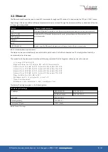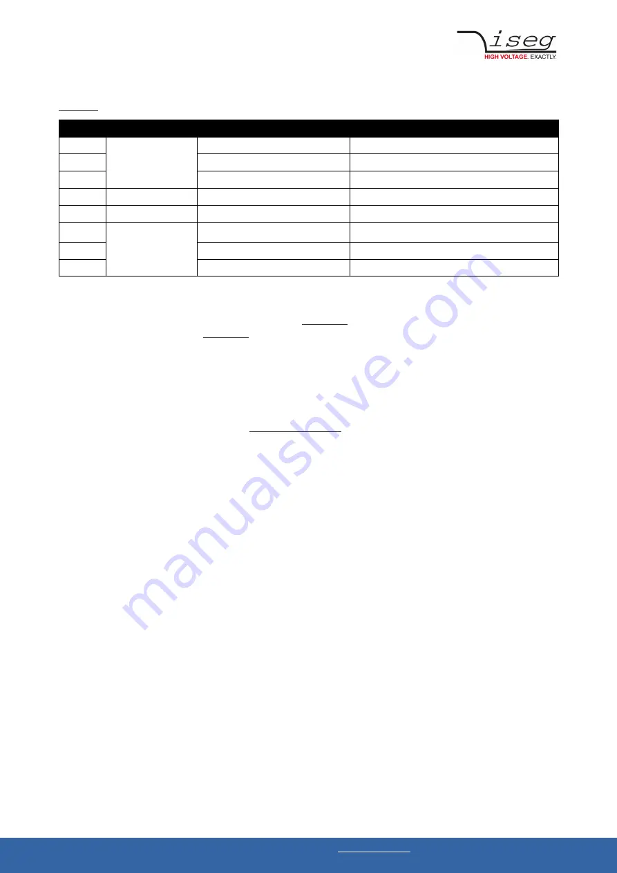
During communication, the HV device acts as a server, the control PC acts as a client. The following table shows the principle TCP
socket communication sequence between PC and HV device. The communication can be monitored with a network analyzer like
, see chapter 12: References.
Step
TCP function call
TCP packet Computer
➜
HV device TCP packet HV device
➜
Computer
1
connect()
SYN
2
SYN, ACK
3
ACK
4
send()
PSH “*IDN?\r\n”
5
recv()
PSH “iseg Spezialelektronik GmbH[…]\r\n”
6
closesocket()
FIN, ACK
7
FIN, ACK
8
ACK
Table 9: TCP communication between computer and HV device
The first three packages establish a TCP connection between Computer and HV device (three way handshake). In the fourth step,
the request from PC is pushed to the HV unit. The command is
(see chapter 11: ASCII character table) in the data field
of the TCP packet. The answer is also
(see chapter 11: ASCII character table) pushed back to the PC in step 5. Here it
is possible that longer answers are transmitted in multiple TCP packets. Step 6 confirms the reception of the packet and sends a
FIN to terminate the connection. Step 7 and 8 are the connection termination confirmation from HV unit and Computer.
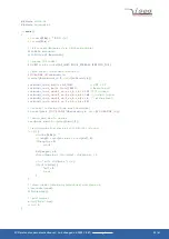
3.2.1 Ethernet programming example
A simple programming example (without error handling) for communication with the HV device over Ethernet is provided. This
program was originally compiled and tested with
on Windows XP, but still works with recent compilers
on newer Windows versions too. Make sure to adopt the device address, which is hard coded to 192.168.16.221 to your
environment.
SCPI protocol common instruction set | Last changed on: 2020-10-07 |
www.iseg-hv.com
22/61

