4 Handling
The unit is set into operating state by connecting at the 96-pin connector according to DIN 41612 on the backside. This also
attaches the RS232 interface. The USB interface is connected via the USB mini B connector on the front panel (below the polarity
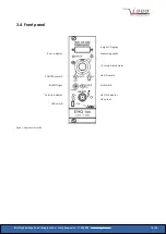
indicator). Before the unit is powered the desired output polarity must be selected by the rotary switch on the cover side
(see appendix, 10 Dimensional drawings). The chosen polarity is displayed by a LED on the front panel and a sign on the LCD.
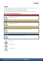
CAUTION!
CAUTION!
It is not allowed to change the polarity under power!
An undefined switch setting (not at one of the end positions) will cause no output voltage.
High voltage output is switched on with HV-ON switch at the front panel. The viability is signalled by the yellow LED.
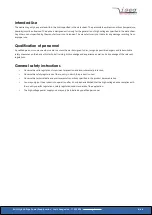
CAUTION!
CAUTION!
If the CONTROL switch is in upper position (manual control), high voltage is generated at the HV-output, started
with a ramp speed from 500 V/s (hardware ramp) to the set voltage given by the 10-turn potentiometer.
This is also the case, if DAC control is switched over to manual control while operating.
If the CONTROL switch is in lower position (DAC), high voltage will be activated only after receiving corresponding serial interface
(DAC) commands.
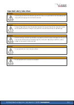
CAUTION!
CAUTION!
If the function “Autostart” has been activated in the previous operating session, the high voltage generation
starts immediately with the saved parameters!
The LCD displays the output voltage in [V] or the output current in [µA]
, depending on the position of the Measuring switch. In
the manual control mode the output voltage can be set via 10-turn potentiometer in a range from 0 to the maximum voltage.
If the CONTROL switch is switched over to serial interface control (DAC), the DAC takes over the last set output voltage of the
manual control. The output voltage can be changed remotely with a programmable ramp speed (software ramp)
from 2 to 255 V/s in a range from 0 to the maximum voltage.
The maximum output current for each channel (current trip) can be set via the remote interface in units of the resolution of the
upper measurement range. If the output current exceeds the programmable limit, the output voltage will be shut off
permanently by the software. A recovery of the voltage is possible after ”
” (7 ISEG instruction set, old
DCP)and then ”
” (7 ISEG instruction set, old DCP) via serial interface. If ”
” (7.4 Auto start) is
active, ”
Start voltage change
” is not necessary.
The maximum output voltage and current can be selected in 10%-steps with the rotary switches V
max
and I
max
(switch dialled to 10
corresponds to 100%) on the cover side (see appendix, 10 Dimensional drawings) independently of programmable current trip.
The red error LED on the front panel signals if the output voltage or current approaches the limits.
1
Option 104, displayed „nA“
EHQ High Voltage Power Supply series | Last changed on: 11.05.2020 |
www.iseg-hv.com
15/46


