


IGEP
TM
RADAR SENSOR ORION Hardware Reference Manual
ISEE 2007
S.L. All rights reserved, IGEP™ is a registered trademark from ISEE 2007 S.L. The following is provided for informational purposes only.
DOCUMENT FROM ISEE 2007 S.L. Ref: MAN-PR-RADR0010-RA1-001
14
ΔF: STEP
, (FREQUENCY STEP): Is the DDS parameter that fixes the RF output frequency
variation that we want from one basic interval to the next one.
RF OUTPUT FREQUENCY VARIATION (
Δ
F[Hz]) is obtained from STEP by the next equation:
Δ
F[Hz]=10
6
*STEP[decimal]*F
0
[MHz]/2^
24
(II)
example: STEP=28 [hexa]
→
Δ
F[kHz]=243,712kHz.
Maximum allowed value of STEP: 400000 [hexa].
NINCR
, NUMBER OF INCREMENTS: Is the number of the RF output frequency increments
we want to have within a modulation sweep. The maximum allowed NINCR is FFF [hexa]
→
4095[decimal].
There are two ways to complete a modulation sweep:
-By controlling the frequency steps through activation of the CTRL port.
-By programming an automatic frequency increment through the next parameter:
SLOPE
: BASIC INTERVAL DURATION: Is the DDS parameter that fix the duration we want for
each basic interval of the modulation sweep (T
BASE
).
T
BASE
is obtained (in nanoseconds) from SLOPE parameter by the next equation:
T
BASE
[ns]=1000*SLOPE[decimal]/F
0
[MHz]
(III)
example: if we want a modulation sweep duration of 10ms with the above value of NINCR (FFF
[hexa]), we should program SLOPE at value '7A' (hexa)
→
122[decimal] → T
BASE
=2,44us →
NINCR[decimal]*T
BASE
= 10ms.
Maximum allowed value for SLOPE is: 7FF [hexa].
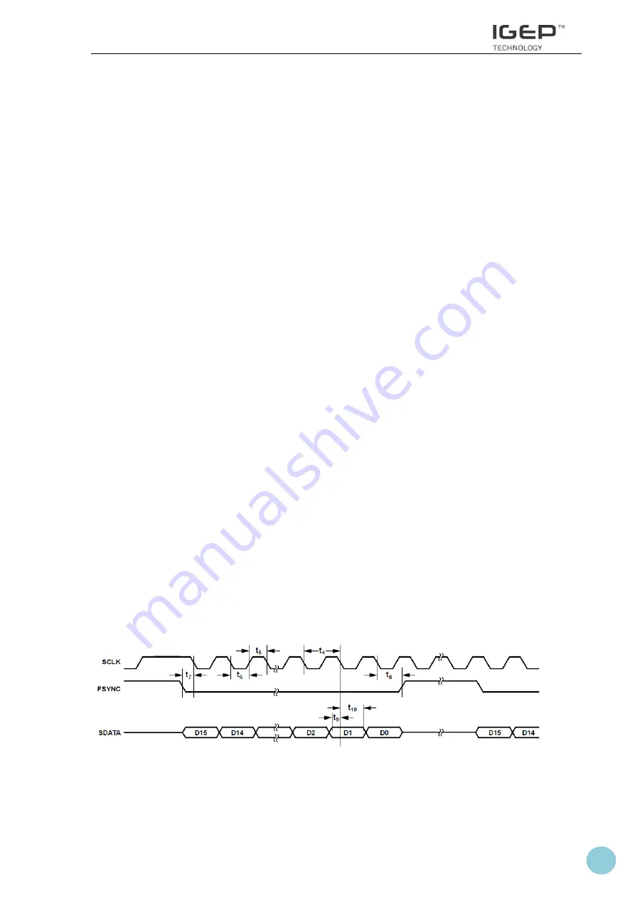
5.6.2
DDS PROGRAMMATION THROUGH SPI LINK
The next figures show the SPI serial interface timing and the basic clock timing:
Figure 7: SPI serial interface signals timing


