background image

Ironwood SLR305  |  User Manual

14

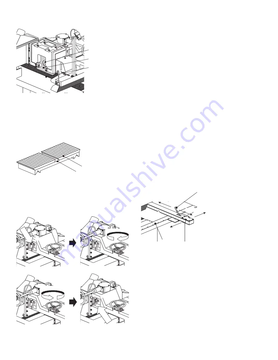
9.  Tighten the hex bolt to secure the saw blade.

Tighten hex bolt

Saw blade

Chain block

10.  Adjust the small pressure rollers to provide support for the 

workpiece near the saw blade and secure with wing nuts.

11.  Lower the arbor until the saw blade teeth are below the feed 

chain by 0.5-1.5mm. Ensure the teeth do not touch the feed 
chain. The rubber inserts in the center of the feed chain allow 
saw blade depth below the surface of the feed chain. 

Chain block

Rubber insert

12.  Lock the saw arbor locking lever.

13.  Close the blade access door and secure.

14.  Remove the saw arbor wrench from the cross slot of the pulley 

and close the rear access door. 

Release

Lock

raise saw arbor

lower saw arbor

To remove the saw blade:

1.  Loosen the saw arbor locking lever.

2.  Open the blade access door.

3.  Raise the saw arbor by turning the saw arbor handwheel so the 

saw blade teeth are 5-10mm higher than the feed chain.

4.  Loosen the wing nuts on the small pressure rollers and move 

them away from the saw blade position.

5.  Open the rear door and fit the supplied saw arbor wrench into 

the cross slot on the pulley for securing the saw arbor.

6.  Loosen the hex bolt securing the lock washer/hub and blade.

7.  Remove the saw blade.

6.2 Attach Rip Fence Assembly

The rip fence assembly attaches to the front of the machine. Use the 
rip fence to position and guide the workpiece as you feed it into the 
machine. The top of the rip fence assembly bracket has a measuring 
scale that indicates the width of the cut (distance between fence and 
saw blade). 

To mount the rip fence assembly:

1.  Hold the assembly up to the front of machine and align it with 

the predrilled holes.

2.  Tighten with the supplied bolts.

3.  Check the fence for squareness to the saw blade and adjust as 

shown below:

Adjustment handle

Lock

Linear
guideway

Release

To lock the rip fence in place, push the handle away from you. To 
release it, pull the handle toward you.

The rip fence should glide easily on the linear guideway for quick and 
easy ripping width adjustment.

Содержание SLR305

Страница 1: ...ollection system operation and adjustments machine controls machine operation rip sawing tips maintenance replace saw arbor motor belt facility preparation work space power delivery and installation i...

Страница 2: ...5 0 Safety 12 6 0 Assembly 13 6 1 Install Saw Blade 6 2 Attach Rip Fence Assembly 6 3 Connect Dust Collection System 7 0 Operation and Adjustments 16 7 1 Machine Controls 7 2 Machine Operation 7 3 Ri...

Страница 3: ...Model_____________________________________________ Machine Serial Number______________________________________ 1 3 Features Cast iron machined feed chain block and guide track 18 ripping width capaci...

Страница 4: ...Hold Down Rollers 6 Rows of Anti Kickback Fingers 3 Working Table Height 32 850mm Saw Arbor Motor 15 hp Saw Arbor Speed 4100 rpm Saw Blade Diameter 10 12 250 330mm Saw Arbor Diameter 1 2 54mm Feed Sp...

Страница 5: ...s Improper use or modifications may affect your warranty or result in serious injury or death Training This machine is intended for use by authorized well trained operators only Do not operate until y...

Страница 6: ...may vary depending on length of material to be cut 2 3 Power WARNING A licensed electrician must connect the SLR305 to the building power source Do not use extension cords Be sure that the electrical...

Страница 7: ...arrive fully crated and secured to a pallet Use a fork lift to move the machine on its pallet as close to its final position as possible If you do not intend to install the Ironwood saw immediately af...

Страница 8: ...nch 5 4 leveling pads 6 4 leveling bolts with nuts 7 Saw arbor wrench 8 Paint 2 color set 9 Fence assembly 10 User manual 3 4 Move Machine to Final Position Be sure the site is properly prepared Refer...

Страница 9: ...n placed at its final location carefully remove the machine from the pallet The machine is bolted to the pallet for transport 1 Remove the bolts securing the machine to the pallet at the 4 corners of...

Страница 10: ...not use gasoline or other petroleum based solvents There is a risk of explosion and burning if these products are used Serious personal injury may occur Use a soft cloth and nonflammable degreasing a...

Страница 11: ...ide terminal box To connect power source to the machine 1 Open the electrical cabinet 2 Place cable through electrical fitting on the bottom of the cabinet 3 Remove the clear plastic insulator that co...

Страница 12: ...dicated by the National Electric Code and local regulating authorities GUARDS Make certain that machine guards are in place and in good working order The machine should never be operated without the s...

Страница 13: ...e saw blade without touching the feed chain 4 Loosen the wing nuts on the small pressure rollers and move them away from the saw blade position 5 Open the rear door and fit the supplied saw arbor wren...

Страница 14: ...the feed chain 4 Loosen the wing nuts on the small pressure rollers and move them away from the saw blade position 5 Open the rear door and fit the supplied saw arbor wrench into the cross slot on th...

Страница 15: ...ube of a suitable dust extraction system to the outlet The dust extraction system should have a flow rate of 4 500 feet min at 600 cfm NOTE Flex hose length should not exceed 30 feet or suction veloci...

Страница 16: ...st the grain 7 1 Machine Controls 1 1 Amp meter for saw motor 10 4 6 9 2 3 5 7 8 2 Power indicator lamp 3 Power source start button 4 Power source stop button 5 Saw blade start button 6 Saw blade stop...

Страница 17: ...afety be sure the top anti kickback fingers hang down in a row point in the direction of the feed chain and can be lifted smoothly Be sure the bottom anti kickback fingers press down and lift up smoot...

Страница 18: ...e has completely stopped before removing material Attempted removal while saw blade is turning may cause kickback The four sides of the workpiece should be even in thickness to obtain a precise straig...

Страница 19: ...age Oil flows from the central lubrication system to the oil distributor which then distributes oil to various points The image below shows the lubrication points and which line lubricates which point...

Страница 20: ...T ION ACT TIME 5 sec 10 sec 15 sec 20 sec 3 min 15 min 20 min 30 min 1 0 0 1 0 0 0 1 0 1 0 1 0 0 1 1 Act time key Int time key Manual pumping switch CESP WIRING DIAGRAM POWER GROUND ABNORMAL OUTPUT PO...

Страница 21: ...the lubricant into the tank until it is 80 full Do not let the lubricant overflow When pouring oil into the tank be sure impurities and debris do not get inside To order oil for the central lubricati...

Страница 22: ...eeks 7 Screw near the arbor Grease with brush Grease Once daily 8 Oil box of gear reducer Fill oil Shell Omala 320 Once monthly 8 3 Inspection Feature Interval Situation Saw blade Daily Belts Every 20...

Страница 23: ...en ended wrench Turn screws clockwise until the old belt can be removed 4 Install a new belt 5 Tighten the two hex head screws 8 7 Feed Chain Cleaning Sawdust dries up lubricant so it is critical to r...

Страница 24: ...saw blade Refer to adjustment section for height adjustment instructions Saw blade has insufficient power Improper saw blade for material or application Saw arbor belt too loose Voltage problem to mo...

Страница 25: ...Ironwood SLR305 User Manual 25 9 1 Electrical Diagrams...

Страница 26: ...Ironwood SLR305 User Manual 26 9 2 Electrical Diagrams Continued...

Страница 27: ...Ironwood SLR305 User Manual 27...

Страница 28: ...Stiles Machinery Inc 3965 44th St SE Grand Rapids MI 49512 p 616 698 7500 f 616 698 9411 www stilesmachinery com 2013 Stiles Machinery Inc Version A September 2013...

Отзывы: