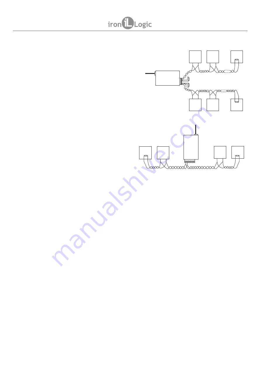
4.3 RS-485 line connection.
5. CONFIGURATION
5.1. Configuration using a text config file.
Note: Do NOT connect more than one Z-397 WEB converter at the same time via PC USB
ports!
Example connection layout for converter using
two RS-485 lines. The converter is at the end
of the line, so a 120-Ohm terminating resistive
load is necessary (supplied with the device).
Example connection layout for converter
plugged into the middle of RS-485 chain.
No terminating resistive load required to
connect to Z-397 WEB.
If the lines are very long, it is necessary
to join ground terminals of converter and
controllers. For that, you can use a single
wire or a pair of wires out of the RS-485
cable used in the lines.
Under the default network settings, the converter is allowed to register automatically onto the LAN.
If the registration is successful, the converter will be ready to work. The ETHERNET status LED will
display solid green in this case.
In case of IP address automatic acquisition failure, ETHERNET indicator will be rapidly flashing
red.
If no DHCP server exists on the network, the automatic configuration is not possible and the
converter parameters must be set manually.
For configuration, please connect the device to a PC via USB cable. In this mode, the USB socket
will provide power to the device and no external power source is necessary.
The device will be detected by the PC, and a new removable disk will appear labelled
“
Z397WEB
”
.
In its root folder, a CONFIG.CFG text file is present containing all device parameters (see Table 1).
If necessary, edit this file with a text editor to ensure correct device operation with these systems.
page 4
Z-397 WEB
www.ironlogic.me
A
B
A
B
Ethernet
R
m
н
,
120
О
R
m
н
,
120
О
Converter
Z-397 WEB
Controller
2
B
A
Controller
N
B
A
Controller
1
B
A
Controller
2
B
A
Controller
N
B
A
Controller
1
B
A
R
m
н
,
120
О
R
m
н
,
120
О
AB
Ethernet
R
m
н
,
120
О
Converter
Z-397 WEB
Controller
4
A
B
Controller
3
A
B
R
m
н
,
120
О
Controller
2
A
B
Controller
1
A
B


