background image

16

Ioline FlexJet User Guide

Cable Connections

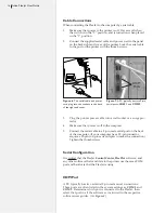
When connecting the FlexJet to the computer by serial cable:
1. 

Make sure that power to the printer is off. Power is off when 

the switch is in the “0” position, and is turned on when placed 

in the “1” position.  

2. 

Connect the supplied serial cable and power cord to the panel 

on the back right end cover of the printer. Lock the serial cable 

to the port on the printer with the thumb screws. 

Figure  6. 

The  serial  cable  and  power 

cord plug into the sockets in the back 

of the right end cover.

Figure 7. 

A PC typically has two 9-pin 

serial ports, 

COM 1

 and 

COM 2

.

3. 

Plug the printer power cable into a wall socket or a surge pro-

tector.

4. 

Make sure that power is off to the computer. 

5. 

Connect the serial cable to a 9-pin male serial port on the back 

of the computer. (If your computer has a 25-pin connector, 

acquire a 25-pin to 9-pin serial adapter to make the connection.) 

Tighten the thumbscrews. 

Serial 

Configuration

It is critical that the FlexJet 

Control Center

FlexPlot

 software, and 

any other software that send data to the printer use the same COM 

port and baud rate that the FlexJet is using. 

COM Port

A PC typically has two external 9-pin male serial connections. 

These ports are often listed in the system settings as 

COM 1

 and 

COM 2

. Determine which port is connected to the FlexJet, then 

select that port in all the software as instructed in the respective 

software user guides. (

See 

Figure 8

.

)

COM
 Ports

Содержание FlexJet

Страница 1: ...User Guide Ioline FlexJet ...

Страница 2: ...performance of the printer and main tain it in proper working condition by following the instructions in this User Guide It is the responsibility of the operator of the printer to follow all safety precautions and warnings that are described in this User Guide Ioline Corporation is not responsible for injuries that may occur as a result of unsafe use Ioline Corporation is not responsible for subst...

Страница 3: ...User Guide Ioline FlexJet ...

Страница 4: ...ng the feed shaft 29 Figure 17 Installing the take up shaft 30 Figure 18 The correct paper feeding path on the Ioline FlexJet printer 31 Figure 19 Taping the paper to the take up shaft 32 Figure 20 Positioning the pinchwheels for 72 in 183 cm paper 33 Figure 21 Inserting the dancer bars 33 Figure 22 Location of dancer bar channels 34 Figure 23 Manually freeing the take up shaft 36 Figure 24 Taping...

Страница 5: ...erview 15 Cable Connections 16 Serial Configuration 16 COM Port 16 Baud Rate 17 Other Serial Port Settings 17 Software Setup Options 17 Power On 19 Installing FlexPlot and the Control Center 19 Chapter 3 Operation Keypad Controls 21 Start Stop 21 Clean 22 Quality 22 Set Origin 22 Arrow Keys 23 Page Advance 23 Unroll 23 Special Key Combinations 23 Roll Up 23 Reset Serial Port Baud Rate 23 Restore F...

Страница 6: ...ert the Dancer Bars 33 Set an Origin 34 Sending Plot Files 34 Pausing a Marker Plot 34 Canceling a Marker Plot 35 Removing Markers from theTake up Shaft 35 Manually Freeing theTake up Shaft 36 Automatically Freeing theTake Up Shaft 37 Reattach Paper to theTake up Shaft 37 Printing to the Floor 38 Chapter 4 Routine Maintenance Cleaning the Drive Shaft 39 Cleaning the PlatenandTraverse 39 Cleaning t...

Страница 7: ...47 Manually Updating Firmware usingTeraTerm 48 Summary 48 Prepare to Update the Firmware 48 Setup TeraTerm 48 Update Firmware 49 Reset CalibrationValues 49 Chapter 5 Troubleshooting GeneralTroubleshooting 51 MediaTracking 51 Printing Quality 52 Line Quality 52 Serial Communication 52 Keypad Error Codes 53 Legend 53 Common Issues 54 Chapter 6 End Notes Service Support 57 Getting Help 57 Customer Se...

Страница 8: ......

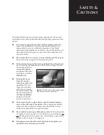
Страница 9: ...otect the print cartridges press the Clean button n Keep hands away from the carriage when the printer is in operation The car riage will automati cally move to touch the left end plate then back to the right end the Service Station position when the power is turned on n Never insert hands or other objects into the Service Station area on the right side of the printer The carriage occasionally ent...

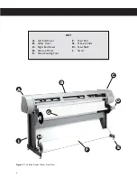
Страница 10: ... Left End Cover B Safety Cover C Right End Cover D Take up Motor E Stand Leveling Foot F Feed Roll G Take up Shaft H Feed Shaft I Stand KEY Figure 2 The Ioline FlexJet Printer FrontView E A B C F H I D G ...

Страница 11: ...he Ioline FlexJet Printer RearView head tilted in maintenance position J Take up Motor Cable K Take up Motor Outlet L Serial USB Ports M Power Switch N Platen Leveling Foot O Cross member P Paper Out Sensors hidden KEY J K L M N xi O P ...

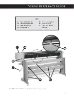
Страница 12: ...fety cover lifted for clarity Q Ink Cartridge Stall R Cartridge Stall Latch S Pinchwheel Lever T Keypad U Service Station Beneath Cover V Take up Sensor W Platen X Pinchwheel Y Drive Shaft Marker Z Traverse AA Carriage Assembly KEY Q T V W AA Z R U S X Y xii ...

Страница 13: ...cording to the directions outlined in the FlexJet Quick Start Guide n A computer system that is properly installed and has a func tioning serial or USB port n Apparel design software loaded into the computer according to the installation instructions n Printing media and ink cartridges that are within the guidelines stated under the Operation chapter n Depending on the communications setup Ioline ...

Страница 14: ...er then rolls the frame segments onto a take up shaft The FlexJet can roll up to 600 yards onto the take up shaft at a time Origin at right side of FlexJet and lower left on plot Left side of FlexJet Right side of FlexJet Figure 5 The X andY axes and origin top view safety cover removed for clarity 4 0 4 7 2 0 4 9 8 In this manual the right and left side refers to the right and left side of the fr...

Страница 15: ... 25 pin serial ports a 25 to 9 pin adapter is necessary Once connected select the correct port and data rate in your apparel design software FlexPlot and or the Control Center Consult the design software manual or the dealer for further information Infor mation on configuring FlexPlot and the Control Center follows in the Operation chapter An overview of the complete setup procedure is described i...

Страница 16: ...er cable into a wall socket or a surge pro tector 4 Make sure that power is off to the computer 5 Connect the serial cable to a 9 pin male serial port on the back of the computer If your computer has a 25 pin connector acquire a 25 pin to 9 pin serial adapter to make the connection Tighten the thumbscrews Serial Configuration It is critical that the FlexJet Control Center FlexPlot software and any...

Страница 17: ...the most robust and flexible workflow available for creating output It s especially useful when many file formats are used a common situation for service bureaus To set up and learn how to use the software see the FlexPlot User Guide The FlexJet is designed to work in many different production envi ronments The type of marker printing you do will often determine your preferred communication method...

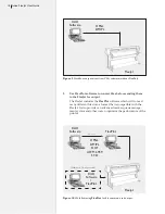
Страница 18: ...e which will convert many different files into a format that is compatible with the FlexJet It also provides an advanced marker queue manage ment system and other tools to optimize the performance of the printer Figure 9 Workflow output direct from CAD software without FlexPlot FlexJet FlexJet CAD Software FlexPlot Network HPGL DM PL DXF ASTM 6959 STD CAD Software HPGL DM PL Alternate Configuratio...

Страница 19: ...adjusting parameters to optimize printer performance The printer comes with a CD ROM which has Microsoft Windows 98 NT 2000 XP versions of the programs as well as PDF user guides and the required Adobe Acrobat reader 1 Power on the computer and Windows 2 Insert the Ioline CD ROM into the CD ROM drive usually D 3 The installation program should start automatically If it does not a Select the Start ...

Страница 20: ...20 Ioline FlexJet User Guide This page intentionally left blank ...

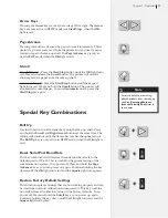
Страница 21: ...ine will stop after it finishes printing the current scan The Arrow Unroll and Paper Advance keys are active when in STOP mode When the Start Stop key is pressed again the printer enters START mode the OK light turns green and printing resumes exactly where it stopped START mode OK green Arrow keys inoperable printer online ready to re ceive instructions STOP mode OK red Arrow keys operable printe...

Страница 22: ...k 600 dpi line mode and Draft mode 300 dpi which prints lighter and consumes less ink You can change line quality while the FlexJet is printing Set Origin The Set Origin key sets the initial origin or starting position for the marker It s best to always set a new origin point after cycling power To set a new origin press Start Stop until the OK light turns red STOP mode Use the Arrow keys to move ...

Страница 23: ...ake up shaft Press and hold the Unroll and Right Arrow buttons at the same time The rolling will continue until the dancer bar reaches the optical sensor The Roll Up key is only active in STOP mode when the OK light is red Reset Serial Port Baud Rate This key combination will restore the serial port baud rate to the default speed of 38 400 This is useful for diagnostic testing of the communication...

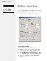
Страница 24: ...are adjustable to fit specific needs n Make sure the printer power is on and that the initialization process is complete The carriage will park the keypad OK light will turn red and the Square light will turn green n The Screen Menu displays the primary settings that are adjust able The Menu Bar contains utilities for setting up the Control Center and calibrating the FlexJet n Changes only take ef...

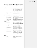
Страница 25: ...r Close Timer Improves Closing communications on some systems Tools Aux Sensor Controls the bottom Paper Out sensor on new FlexJets or the Cover Sensor on old FlexJets Cartridge Calibration Displays tools to adjust print cartridge alignment See Routine Maintenance for more details Size Calibration Allows adjustment of the size cali bration settings See Routine Main tenance for more details About Y...

Страница 26: ... breaking them into smaller pieces called frames In general design software does this automatically and adjusts the Frame Size in the printer to match The Frame Size setting establishes clipping limits for each data frame If the printed size of a plot frame exceeds the frame size set in the FlexJet the excess is clipped or thrown away If the plot is clipped try increasing the Frame Size manually T...

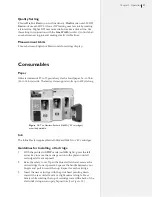
Страница 27: ...s up to 600 yds long Ink The Ioline FlexJet requires Hewlett Packard 51645A or 45 cartridges Guidelines for Installing a Cartridge 1 With the printer in STOP mode red OK light press the left arrow key to move the carriage out onto the platen until all cartridge stalls are exposed 2 Raise the safety cover Open the blue stall latch and remove the old cartridge if one is present Squeeze the handle be...

Страница 28: ... the next several sections In most cases the design files are sent to the printer from FlexPlot or the design ap plication If necessary use the Ioline Control Center to send design files or adjust settings General Guidelines 1 Good paper loading makes good plots Follow loading instruc tions carefully 2 Ensure that the paper roll is centered on the feed shaft by align ing the paper hub with the gui...

Страница 29: ...eed shaft through the paper hubs and the paper roll If a paper hub falls out press it firmly back into the end of the paper roll and reseat it with a rubber mallet 4 This step is very important Center the paper roll on the feed shaft by aligning the hubs with the black markings on the feed shaft Make sure the hubs remain securely in place Figure 16 Installing the feed shaft Support Block apply gre...

Страница 30: ...nroll key to rotate the take up key until it is oriented perpendicular to the support block opening as shown in Figure 17 4 Put the take up shaft into the front support blocks with the flanged coupling at the right keypad end Rotate the shaft until the slot in the flanged coupling is aligned with the take up key When the shaft slot and the key are aligned push the take up shaft into place until it...

Страница 31: ...ss the Clean button 2 If the pinchwheels are lowered raise them by pushing the pinchwheel lever away from the machine 3 Pull a long leader of paper off of the paper roll and insert it through the stand behind the plotting head over the rear top bar and between the platen and pinchwheels 4 Temporarily lock the paper in place by pulling the pinchwheel lever toward the machine to lower the pinchwheel...

Страница 32: ... until the tension feels even 7 Press and hold the paper on the center of the platen with your left hand then lower the pinchwheels to lock the paper in place 8 Attach the paper to the take up shaft in the center and 2 in 5 cm from each end with the tape Figure 19 Taping the paper to the take up shaft Tape the paper in 3 places Positioning the Pinchwheels Pinchwheel position should correspond to p...

Страница 33: ...ace over the rear top bar and insert the rear heavy gray dancer bar into the rear dancer bar channel Apply gentle pressure to control the paper feed as gravity pulls the heavy bar into the channel See Figure 21 3 Insert the front dancer bar into the front dancer bar channels Inner Pinchwheel Figure 20 Positioning the pinchwheels for 72 in 183 cm paper 72 Inch Paper Outer Pinchwheels White Drivesha...

Страница 34: ...on and that the printer is in Start mode green light From FlexPlot 1 Choose input file type and location then double click on the file 2 Conversion will occur and the Send to Queue button is acti vated Press this button to add the file to the queue 3 Repeat steps 1 to 2 until the Queue contains all files you wish to print 4 Press the Send button Pausing a Marker Plot 1 Pause a plot by pressing the...

Страница 35: ...lace Method 2 Manual unroll with the Unroll key a Press the Unroll key to unroll full markers in short steps b Cut the marker free from the take up shaft Reattach the paper to the take up shaft with masking tape following the steps outlined under the section Reattach Paper to the Take up Shaft later in this chapter before continuing printing Method 3 Automatic Unroll with the Unroll Key a Press an...

Страница 36: ...cular to the opening in the sup port block see Figure 17 Remove the shaft 3 Stand the roll on end with the flanged coupling pointing up Ro tate the take up shaft counter clockwise opposite to the direction that the paper was rolled on the machine See Figure 23 4 The larger the roll the more rotations are required to free the shaft When the shaft freely rotates lay the roll on the ground 5 Continue...

Страница 37: ...ndicular to the opening in the support block see Figure 17 Remove the shaft and lay it on the ground 5 Continue to twist the shaft counter clockwise while pulling it out of the paper roll until it is free Reattach Paper to theTake up Shaft 1 Use the Page Advance key to drive enough paper forward to drape over the gray top bar and wrap under and around the take up shaft 2 Guide the paper over the g...

Страница 38: ...s shown in Figure 24 2 Use the paper path diagram to thread the paper on the front of the machine It should drape over the front top bar AND the empty take up shaft 3 Set an origin normally and begin plotting Make sure that the paper piles smoothly onto the floor If it bunches up it may catch on the moving carriage and tear Figure 25 Paper path for printing to the floor If the paper bubbles or wri...

Страница 39: ...ulate on the platen and traverse Un der regular use clean every two weeks 1 Turn off power to the printer 2 Dampen a lint free cloth with isopropyl pharmacy alcohol and gently wipe the platen and traverse rails until accumulated residue is removed Warning Do not use water brushes with metal bristles or solvents ex cept isopropyl pharmacy al cohol to clean the printer Keep the drive shaft bearings ...

Страница 40: ...with the printer 3 in 1 brand oil is also a very good lubricant for the feed block 5 Wipe down both ends of the feed and take up shafts before reinstalling them Size Calibration Over time the printer may require calibration to account for normal wear Calibration adjusts the output to match design intent Prepare the Printer See the Operation chapter 1 Load the printer with at minimum 46 in wide pap...

Страница 41: ...0 in 2 39 725 in The X calibration value is the average 39 725 in Enter the Calibration Data 1 Enter the measured values in the boxes in the Calibration win dow Make sure the printer is in START green light mode Select the Set Calibration button 2 The Control Center will send the calibration values to the printer and the new Calibration Setting will be displayed in the boxes in the window pictured...

Страница 42: ... to communicate with the printer If errors occur check the cables and ensure that the cor rect port number and baud rate are selected See Connect the FlexJet to the Computer Overview in the Installation chapter for information on serial port connections Figure 29 Cartridge calibration window Cartridge Calibration There are three types of adjustments associated with the ink cartridges Most line qua...

Страница 43: ...m the number displayed in the box negative numbers are okay and enter it in the Cartridge 2 window c Press the Set Alignment button d Resend the 40X8 plt test file to ensure the results are satisfactory Repeat until the results are correct 7 Perform the Frame Gap adjustment detailed later in this chap ter to reset the Frame Gap Motion Adjust Carriage Scan Alignment 1 Press Select Alignment Plot 2 ...

Страница 44: ...nt cartridge and eventually will degrade plot quality In addition when print cartridges sit inactive for a period of time ink may dry in the nozzles and create an ink plug This results in the appearance of white streaks in the printed text or graphic Check Cartridges If you experience print quality problems first verify that the ink cartridge s is undamaged and is not out of ink 1 Press the Start ...

Страница 45: ...ng chambers A Cloth Should Be n Soft fiberless and moistened with deionized water Should NOT Be n Abrasive made of small fibers dry nor contain chemical additives 1 Press the Start Stop key 2 Using the Left Arrow key reposition the carriage over the platen 3 Open the latch for the first cartridge and remove it 4 Inspect the ink level indicator on the cartridge to verify the cartridge is not empty ...

Страница 46: ... the PC and FlexJet 2 Ensure that the serial cable is connected between the PC and the FlexJet 3 Copy the firmware file to the folder c Ioline Firmware or another location that is easy to remember Check the Current FirmwareVersion 1 Start the FlexJet Control Center 2 The main screen shows the current firmware version in the upper right corner If the version is less than 253 2 then please follow th...

Страница 47: ...to browse to the location where you stored the firmware file e g c Ioline Firmware 5 A download progress window will appear 6 When the download finishes the printer will go through the initialization process When the FlexJet is finished the OK light will turn red and the Square light will turn green 7 Press the Done button 8 The FlexJet is ready for normal use Perform test plots and verify that th...

Страница 48: ...raTerm Please contact Ioline if you need a copy It is included on the FlexJet CDROM in the X tools where X is the CDROM drive letter folder 2 When the New Connection window appears click on the circle next to Serial then select the COM port that connects the printer to the PC 3 In the main TeraTerm window menu click on Setup Serial Port 4 Make sure the settings match the following a Data 8 bit b P...

Страница 49: ...K light turns red and the Square light turns green 8 The FlexJet is ready for normal use Perform test plots and verify that the calibration values are correct If anything is not performing correctly reset calibration values as described un der the Reset Calibration Values section in this chapter Reset CalibrationValues Perform the steps below if calibration values have been altered 1 With the Flex...

Страница 50: ...50 Ioline FlexJet User Guide Figure 34 Factory calibration values on the sticker inside the Service Station ...

Страница 51: ...he Operation chapter for more details n Make sure the paper path and dancer bars are set correctly as shown in Figures 18 and 25 n Inspect the paper for wrinkles or folds Never use paper that is folded wrinkled or torn in any way It may cause paper jams n Make sure the pinchwheels are spaced across the paper as outlined under the Operation chapter n The pinchwheels should never be positioned over ...

Страница 52: ... with a de ionized water moistened lint free cloth See Cartridge Maintenance and Handling under the Routine Maintenance chapter for more information 4 Plot on undamaged or higher quality paper that is free of wrinkles and bubbles 5 Use genuine HP 45 cartridges as recommended by Ioline 6 Contact an Ioline distributor or Ioline Customer Service if you need further help Serial Communication The seria...

Страница 53: ...ff System Stop 2 Press and hold the Page Advance key while turning power on 3 Continue holding the Page Advance key until the OK light turns red and the Square light turns green 4 Cycle power again do not touch any keys this time to ensure communications are reset If using a terminal program like TeraTerm to communicate with the FlexJet make sure to use 8 Data Bits No Parity 1 Stop Bit and Xon Xof...

Страница 54: ...unication problem has oc curred or the printer is in STOP red light mode Solution Make certain the communication port is connected and configured properly Position the pen where the plot should start and press the Set Origin key to put the printer in START green light mode No power when printer is turned on keypad lights stay dark Cause 1 The power cord is damaged or disconnected 2 The printer is ...

Страница 55: ...ouching the feed roll and that the rear top bar rotates freely 5 Clean then lubricate the feed shaft block Use the included white lithium grease 6 Load paper straight as described in the Operation chapter 7 Adjust paper to go between the front and rear cross members Gap between each scan Cause 1 Frame Gap setting is incorrect 2 Ink cartridge is out of ink dirty or the print head is plugged Solutio...

Страница 56: ...t optical sensor before plotting 7 Make sure the distance between the print heads and platen sur face is the same at both the right and left side of the printer Adjust the platen levelers as described in the FlexJet Quick Start Guide 8 Use the Control Center to check the firmware version and ensure it is 324 or greater 9 With power off raise the pinchwheels and align them with the white driveshaft...

Страница 57: ...er Customer Service in this chapter Any warranty servicing of this product not specifically described in this manual must be authorized in writing by Ioline Customer Service You may obtain service by calling or faxing Ioline Customer Service The technicians will help you determine the nature of the problem If factory repair is necessary you will receive a RMA Re turn Material Authorization Please ...

Страница 58: ...ine Customer Service Department Monday through Friday 7 00 A M 5 00 P M U S Pacific Time Voice 1 425 398 8282 Fax 1 425 398 8383 support ioline com www ioline com Your Comments Are Requested Ioline Corporation is interested in comments on our documentation and products Please send corrections or suggestions to Ioline Corporation 14140 NE 200th Street Woodinville WA 98072 USA Voice 1 425 398 8282 F...

Страница 59: ... used Type of Computer Type of design software New software or peripherals Service history Before you contact Support Please gather the following information about your printer before contacting Ioline or your dealer for technical support You ll find the serial number above the power switch on the back side of the right cover ...

Страница 60: ...ost computer and receiver are on different branch circuits If necessary consult the dealer or an experienced radio television technician for additional suggestions How To Identify and Resolve Radio TV Interference Problems a booklet published by the Federal Communications Commission is a helpful reference Please contact the FCC to request a copy www fcc gov Document stock number 004 000 00345 4 Th...

Страница 61: ...the material Glossary F Feed Loop Slack material between the feed roll and the printer The rear dancer bar holds the feed loop taut during printing Feed Shaft Metal rod that holds the paper roll parallel to the printer and allows it to turn during feeding File Name Extensions In DOS and Windows based programs the three letters after the period in a file name With graphics files the three letters d...

Страница 62: ...R Rear Dancer Bar Heavy rod that holds the paper feed loop taught Red Light Mode See STOP Mode Resolution The smallest distance that a printer can move the material or the carriage Printer resolution affects the accuracy of plot file reproduction on the material Roll Feed A method of pulling material from a roll for printing Works in conjunction with the rear dancer bar and drive shaft S Scan A si...

Страница 63: ...l bars in the front and rear of the printer that hold the feed loop and take up loop vertical Traverse Structure that supports and guides the carriage and holds the pinchwheel assemblies U USB Universal Serial Bus High speed method for transferring information from a PC to a peripheral like a printer V Vector A line segment between two coordinates X X Axis Theoretical horizontal line providing a l...

Страница 64: ...64 Ioline FlexJet User Guide This page intentionally left blank ...

Страница 65: ...ion window in Control Center 42 Control Center calibration screen 40 Factory default settings 41 50 Calibration sticker 50 Ink cartridges 42 Measuring the calibration box 41 Motion adjust box 43 Plot size 40 Calibration box 43 44 Calibration folder 43 44 Calibration sticker 50 Cancel a print job 35 Carriage ix xii 14 19 22 23 24 26 27 29 31 34 35 38 40 41 42 44 45 49 53 55 56 61 62 63 Close up vie...

Страница 66: ... firmware 25 Exit 25 Frame size 26 Get plotter data 26 Help about 25 Installation 19 Line width 26 Main Menu 24 Measurement units 27 Menu Bar 25 Menu options 26 Quality setting 27 Scale 26 Screen Menu 24 Send command 25 Send plot file 25 Set key code 25 Set machine ID 25 Settings 25 Size calibration 25 Software version 26 Control panel 21 61 See also Keypad Conversion 13 18 Coordinate 61 Cross mem...

Страница 67: ...t Set up Operating and MaintenanceVideo 15 FlexPlot 13 15 16 17 18 19 28 34 35 52 See also the FlexPlot User Guide Abort button 35 Installation 19 Send to queue 34 Set up window 17 Workflow using CAD software 18 Workflow with FlexPlot 18 Flow control 17 48 53 Font 61 Foot Platen leveling foot close up xi Stand leveling foot close up x Frame 61 See also Plot Frame gap 42 Eliminating or adjusting 44...

Страница 68: ...ult settings 23 Roll Up 23 Set origin 22 34 35 40 42 54 56 62 Special key combinations 23 Square light 19 23 24 29 34 53 Start Stop 21 22 23 31 34 35 44 45 52 62 Unroll 21 23 30 35 37 49 Keypad error codes 53 L Left end cover x License key code 25 Limit of liability statement x Line quality See Printing Quality See also Troubleshooting Line width 24 26 27 43 See also Printing Quality Loop Length 2...

Страница 69: ...56 63 Accuracy 14 Adjustments with Control Center 24 26 Carriage motion 14 Frame 14 26 54 55 Alignment 42 Frame size 26 61 Scan gaps See Troubleshooting Layout 14 Line width 24 26 27 43 Paper motion 14 62 Quality See Printing Quality Removal See Unroll Scale 24 26 Scan 62 Alignment 44 Sending to printer 24 34 Set origin 22 X axis 14 26 41 Y axis 14 26 41 61 Plotter settings 13 15 16 17 19 24 25 26...

Страница 70: ...nd 25 Sending plot files 34 Send plot file 25 Send size plot 41 Send to queue 34 Sensor xii 23 62 Serial communication 62 See also Communications Serial port xi 13 15 16 17 23 52 62 Configuration 16 Data bits 17 FlexPlot set up window 17 Flow control 17 Location on computer 16 Location on FlexJet 16 Parity 17 Setup 16 17 Stop bits 17 Service loop 62 See also Feed loop Service Station ix xii 19 22 ...

Страница 71: ...ake up shaft 36 Maximum paper roll length 14 Taping paper to take up shaft 32 Tape positions 32 Tech Support 58 TeraTerm 48 49 Terminal program 17 53 Throughput 63 Top bar 63 Tracking 51 56 Traverse xii 39 63 Cleaning 39 Troubleshooting 51 56 See also FlexJet Service Manual Alignment issues 55 Common issues 54 56 Communications 52 General troubleshooting 51 Keypad error codes 53 55 Loss of registr...

Отзывы: