Invicta IPC-S Скачать руководство пользователя страница 27


27 

Symbol Identification and Operational Information. 

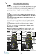
Refer also to Figs.30a and 30b on page 26 and the diagnostic table on page 28. 

Symbol 

Details 


The

  Battery  Gauge 

shows that the wheelchair is switched 

“On”.  It  also  indicates  the  operating  status  of  the 

wheelchair. 


The


“ON  /  OFF”  Button 

is  operated  by  depressing  the 

button  once  to  switch  the  power  “ON”  and  depressing  the 
button again to switch the power “OFF”. 


When  switched  “ON”,  this  applies  power  to  the  Control 

System  electronics,  which  in  turn  supplies  power  to  the 

wheelchair’s motors.


Unless  there  is  an  emergency,  DO  NOT  use  the  “ON  / 
OFF”  button  to  stop  the  wheelchair,  as  this  could  shorten 

the life of the drive components.    


The

  Joystick 

primary function is to control the speed and 

direction  of  the  wheelchair.  The  further  you  push  the 
Joystick from the centre position, the faster the wheelchair 
will  move.  When  the  Joystick  is  released,  the  brakes  are 
automatically applied. 
If the wheelchair is fitted with an actuator, the Joystick may 
also be used to select the actuator direction.   


The

 Horn Button 

will sound the horn when the button is 

depressed. 


The 

Profile  Indicator 

is  an  indicator  that  shows  the 

selected  drive  profile.  There  may  be  up  to  five  profiles 
available,  this  depends on  the  programming  of the  Control 
System. 


The 

Maximum  Speed  /  Profile  Indicator 

is a gauge that 

shows the maximum speed setting for the wheelchair or, if 
the  Control  system  is  programmed  for  drive  profile 
operation, the selected drive profile. 

Speed  Profile  Buttons

To 

increase

  the  speed  profile, 

depress the Right-hand Button once for each speed range 
increase.  The  indicator  lights  will  inform  you  of  the  current 
level range setting.  
Depressing  the  Left-hand  Button  will 

decrease

  the  speed 

range one level for each depression. 


The 

Actuator  Buttons 

allow  the  User  to  depress  either 

Button  to  enter  the  adjustment  mode  and  this  will  be 
indicated by illumination of both actuator LEDs. 
The Seat Tilt actuator can now be operated by the forward 
and rearward movement of the Joystick. Fig.30b only 


Содержание IPC-S

Страница 1: ...Powered Wheelchairs Instructions for Use Models IPC S and IPC T Edition Two Feb 2013...

Страница 2: ...2...

Страница 3: ...sponsibility 7 Warranty Terms and Conditions 7 Service Information 8 CE Declaration 8 Safety General Safety Instructions 9 Electromagnetic Compatibility 10 Environmental Conditions 10 Transferring to...

Страница 4: ...r Suspension Fig 2 12 Width Adjustable Seat Frame Fig 2 12 Footrest Hangers and Footrests Fig 3a 13 Lock Mechanism for Seat Base Fig 3a 13 Retaining Lap Belt Fig 3a 13 Seat Board and Cushion Fig 3a 13...

Страница 5: ...y to Drive 29 Driving Technique 30 Maintenance Intervals 31 32 Parking Brake Adjustment 33 Inspection and Security of Drive Wheels 33 Inspection and Security of Front Castors 34 Inspection of Drive Mo...

Страница 6: ...ning of Users and Carers by suitably qualified personnel is essential to ensure correct and safe operation of the wheelchair Invicta IPC S and IPC T models must only be used in conjunction with approv...

Страница 7: ...e classed as consumable items and will only be considered for repair or replacement under warranty where a failure is clearly identified as being a direct result of a manufacturing or material defect...

Страница 8: ...C T marketed in the UK solely by Rehabilitation Manufacturing Services Limited conform to Class 1 requirements of Council Directive 93 42 EEC of 14th June 1993 concerning medical devices Are in confor...

Страница 9: ...obstacle climbing height is 50mm 2 inches To exceed either of these limits could severly affect the overall stability of the wheelchair causing it to tip and lead to possible injury to the User Do NOT...

Страница 10: ...hair including uncontrollable directional control or unexpected release of the electromagnetic brakes should be reported to your wheelchair supplier as soon as possible Environmental Conditions Enviro...

Страница 11: ...s or outwards for any object which would require lifting their body weight off the wheelchair seat as this would change the centre of gravity and could therefore affect the wheelchair stability Leanin...

Страница 12: ...Tie down Brackets Angle Adjustable Backrest 90 to 135 Front Transportation Tie down Brackets Puncture Proof Tyres Front Rear Two 31Amp hr Gel Batteries Rear Suspension Adjustable Seat Depth Width Adj...

Страница 13: ...tify your specific model 13 MAIN COMPONENT IDENTIFICATION Fig 3a Tension Adjustable Backrest Retaining Lap Belt Seat Board with Velcro attached Contoured Cushion Lock Mechanism for Removable Seat Swin...

Страница 14: ...ir Lap or Pelvic Belt be used as the sole method of occupant restraint The safe occupant weight limit for transportation in the Invicta is 50Kg Although the Invicta Wheelchair Crash Tests were carried...

Страница 15: ...Figs 12 15 For ease of working remove both Sidearms and both Footrest Hangers Fig 1 Remove Seat Base Panel retaining screws x 6 Fig 6 and lift Panel off Frame Remove screws and nuts a x 2 and slacken...

Страница 16: ...set to the Drive position Fig 16 Tools Required 13mm Spanner 4 and 6mm Hexagon Keys For ease of working remove both Sidearms Fig 1 Remove Velcro attached Seat Cushion Remove Seat Base Panel retaining...

Страница 17: ...135 Fig 10 Adjustment is made by slackening screws a Fig 18 and removing screws b to allow the Backrest to pivot around screw a until one of the two holes in the lower Backrest Frame aligns with the a...

Страница 18: ...ded panel with motive Fig 14 upwards at the rear of the Backrest towards the top Finally folding the last panel over the top of the Backrest and securing to the front of the via the Velcro panels Wher...

Страница 19: ...is refitted to the same angle as before With the Frame disconnected lift clear and slide lower Adjustment Panel off the Frame Re install Backrest Frame to the Connecting Plates using the original scr...

Страница 20: ...rom the wheelchair leaving just the Hanger Mounts attached to the Seat Frame Fig 17a Remove screws and nuts a and slacken grub screws b Slide Hanger Mount in or out of the Seat Frame to the nearest re...

Страница 21: ...e Hanger to the required position Re tighten grub screw sufficiently to prevent movement NOTE Ensure there is at least 40mm of Footrest Stem inside the Hangers before tightening grub screws Footrest A...

Страница 22: ...ector Fig 21 The Power Tilt Actuator Cable on the IPC T model must also be disconnected at the white black connector Fig 22 Both located just forward of the rear main Chassis Remove both Sidearms comp...

Страница 23: ...26 Re installation of the Batteries is by the reverse step by step of the removal procedures On completion of reassembly and final connection of cables ensure the Drive Selector Lever Fig 2 is set in...

Страница 24: ...also has built in status indication with the following signals Battery Gauge is Steady This indicates that all is well Battery Gauge Flashes Slowly The control system is functioning correctly but you...

Страница 25: ...r cord with round plug to safely reach the socket on the underside of the Remote Controller Fig 28b Connect the Charger Power Cable to the Remote Controller Fig 28b and plug Mains cable into the Mains...

Страница 26: ...ables Your Control System uses industrial grade components throughout ensuring reliable operation in a wide range of conditions However you will improve the reliability of the Control System if you ke...

Страница 27: ...lly applied If the wheelchair is fitted with an actuator the Joystick may also be used to select the actuator direction The Horn Button will sound the horn when the button is depressed The Profile Ind...

Страница 28: ...d Motor has a bad connection Check connections to the Right hand Motor 5 BAR The Right hand Motor has a short circuit to a Battery connection Contact your Service Agent 6 BAR The wheelchair is being p...

Страница 29: ...earm to be repositioned upwards or downwards Retighten Thumb screw ensuring the screw thread engages into the required positioning hole To set the Remote Controller in the correct position slacken bot...

Страница 30: ...as above this could affect the dynamic stability of the wheelchair NEVER attempt to negotiate steps or stairs Do not drive your wheelchair in places or on surfaces where a loss of wheel grip could occ...

Страница 31: ...page 24 Component Security Confirm security of Sidearms Footrest Hangers and Footplates Also correct adjustment of the Lap Belt and any positioning Harness or Foot Control devices when fitted Cables I...

Страница 32: ...cess movement and smooth turning Fig 34 page 34 Check that the wheels spin freely and without axial run out Drive Motor Brushes To avoid possible damage to the Drive Motors it is recommended by the Mo...

Страница 33: ...d in this position and while ensuring the Brake Bar is at 90 to the tyre retighten both Brake Mounting Clamp screws sufficiently to prevent any movement Repeat this procedure for the opposite side App...

Страница 34: ...gent and thereafter at 6 monthly intervals to maintain peak Motor performance Each Drive Motor is fitted with two Brushes however as access to the inner Brush Retaining Cap is limited by the Battery C...

Страница 35: ...he RMS PB002 with single Pull tight plastic buckle Separate the Belt at the main buckle by depressing the locking tongue Fig 438 With the User seated route each end of the Lap Belt up and over the Use...

Страница 36: ...disinfectant added DO NOT USE any scrubbing agents DO NOT USE high pressure cleaning devices DO NOT subject the electronic components to direct contact with water Wipe off all cleaned areas with a cl...

Страница 37: ...een maintained according to the manufacturer s recommendations When the time comes to replace your wheelchair please remember to dispose of the device responsibly and recycle as many parts as possible...

Страница 38: ...7cm Maximum Obstacle Climbing 5cm Dynamic Stability 10 Front Castor Wheels with puncture proof tyres unless otherwise requested 200 x 50mm Rear Drive Wheels with puncture proof tyres unless otherwise...

Страница 39: ...ack Powder Coating Chassis Frame Aluminium finished in Silver Metallic Powder Coating INVICTA IPC T Tilt in Space Model Seat Width 30cm Std Seat Depth 29cm adjustable Seat Width 35 5cm Std Seat Depth...

Страница 40: ...ional Brackets Padded Pelvic Belts Harnesses Butterfly Sternum Shoulder Dynamic Alternative Remote Controllers Attendant Controller Mid line Controller mounted to Clear Plastic tray Attendant Hand hel...

Страница 41: ...41 USER NOTES...

Страница 42: ...USER NOTES...

Страница 43: ...USER NOTES...

Страница 44: ...Powered Wheelchairs MEDWAY HOUSE 277 Gillingham Road Gillingham Kent ME7 4QX Tel 01634 578881 Fax 01634 581456 Email address sales rms kent co uk...

Отзывы: