23
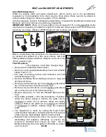
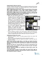
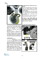
Each Battery Box can now be removed
from the wheelchair by sliding the Box
along the supporting rails and out from
the rear of the wheelchair Fig.25.
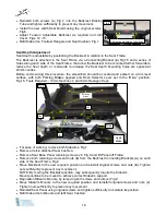
The individual Batteries can then be
accessed, by releasing the strap
buckles (
e
) Fig.25, retaining the
Battery Box Covers and removing the
Covers.
Disconnect the power cables from the
Batteries and lift Batteries out from
their Boxes.
IMPORTANT NOTE:
If the Batteries are
to be replaced, the new ones must be of
the same type, physical size, capacity
and
terminal
configuration.
It
is
recommended that both Batteries are
replaced at the same time and ideally,
they should be fully charged by the
supplier before installation.
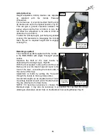
Ensure Main Battery Cables are correctly
connected to the Batteries and the
terminal screws are fully tightened. Fig.26
Re-installation of the Batteries is by the
reverse, step by step, of the removal
procedures.
On completion of reassembly and final
connection of cables, ensure the Drive
Selector Lever Fig.2, is set in the forward
“Drive” position and the Manual Parking
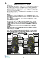
Brakes are applied. Switch “ON” the
power at the Remote Controller Fig.20,
(ensure Joy Stick is in the central
position) to check the Battery charge
level on the indicator. Figs.27a, b and c.
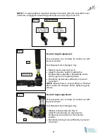
Each Battery Box is fitted with an
overload Reset Button, Figs 26a and 26b.
As these are safety devices, if either
device trips-out more than once, then try
to note what was operating when it
tripped-out as this may assist with fault
diagnosis.
The Buttons can be reset by depressing,
after the fault has been rectified.
[Cont]
Main Battery
connectors
Fig. 23
Fig. 24
Battery Box
retaining straps
Battery Box
retaining straps
Battery Box retaining bracket
with hand screws
a
b
c
d
Fig. 25
Battery Box Cover
Retaining Straps
e
e
Fig. 26
Fig. 26a
Fig. 26b
Front
Rear
Содержание IPC-S
Страница 1: ...Powered Wheelchairs Instructions for Use Models IPC S and IPC T Edition Two Feb 2013...
Страница 2: ...2...
Страница 41: ...41 USER NOTES...
Страница 42: ...USER NOTES...
Страница 43: ...USER NOTES...


