


Version 1.00
| Optidrive CoolVert User Guide |
39
www.invertekdrives.com
4
Set-up and Operation
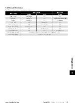
Par
Mod
Add Description
Def
Min
Max
Unit
R/W
6-06
606 Fieldbus Ramp Control Enable
0
0
1
-
R/W
Selects whether the acceleration and deceleration ramps are control directly via the Fieldbus, or by internal drive
parameters.
0: Disabled.
Ramps are control from internal drive parameters.
1: Enabled.
Ramps are controlled directly by the Fieldbus.
6-07
607 Modbus Response Delay
0
0
16
Char
R/W
Defines the response delay time for Modbus communications. The value entered represents the delay expressed
as the number of characters added to the minimum permitted Modbus response delay time.
The actual delay time will vary depending on the Modbus communications baudrate.
4.4.7. Group 7 Parameters & Modbus Registers
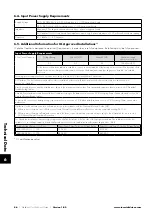
Par
Mod
Add Description
Def
Min
Max
Unit
R/W
7-01
701
Automatic Thermal Management Minimum
Switching Frequency
0
0
6
-
R/W
During operation, the drive measures the power module temperature and will switch automatically to a lower
switching frequency if the temperature reaches a pre-defined limit. This parameter determines the lowest
frequency that can be used. In the event that the power module temperature continues to increase, the drive will
trip on over temperature.
7-02
702 Auto-reset Time Delay
20
1
60
S
R/W
Sets the delay time which will elapse between consecutive drive reset attempts when Auto Reset is enabled in
P2-13.
7-03
703 Motor Stator Resistance (Rs)
-
0.00 655.35 ohm
R/W
This is the motor phase to phase resistance value in ohms.
7-04
704 Motor Stator Inductance (Lsd)
-
0.0
6553.5
mH
R/W
For induction motors: phase stator inductance value.
For permanent magnet motors: phase d-axis stator inductance in Henry (H).
7-05
705 Motor Stator Inductance (Lsq)
-
0.0
6553.5
mH
R/W
For permanent magnet motors : phase d-axis stator inductance in Henry (H).
7-06
706 V/F Mode Magnetising Delay Time
-
0
5000
Ms
R/W
This parameter is used to set up a minimum delay time for the magnetising current control in V/F mode when
drive run signal is given. Too small a value may cause the drive to trip on over-current if the acceleration ramp is
very short.
7-07
707 Low Frequency Torque Boost Level
0.0
0.0
100
%
R/W
Boost current applied at start-up, as % of motor rated current (P1-08). The drive provides a boost function that
can inject some current into the motor at low speed to help ensure the rotor alignment is maintained and to allow
effective operation of the motor at lower speeds. To implement low speed boost, run the drive at the lowest
frequency required by the application and increase boost levels to provide both required torque and smooth
operation.
7-08
708 Low Frequency Torque Boost, Frequency Limit
0.0
0.0
50
%
R/W
Frequency range for applied boost current (P7-07) as a %age of motor rated frequency (P1-09). This sets the
frequency cut-off point above which boost current is no longer applied to the motor.


