Version 1.00
| Optidrive CoolVert User Guide |
31
www.invertekdrives.com
4
Set-up and Operation
4.4. Full Parameter List and Modbus Registers
4.4.1. Group 1 Parameters & Modbus Registers
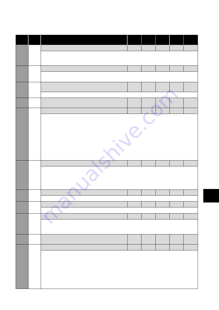
Par
Mod
Add Description
Def
Min
Max
Unit
R/W
1-01
101
Maximum Speed Limit
60
P1-02
500
Rps
R/W
Sets the upper limit for the speed of the motor in rps (revolutions per second).
This can be set to any value between the minimum speed limit (P1-02) and 5x the motor rated speed (as set in
P1-10).
1-02
102
Minimum Speed Limit
20-
0
P1-01
Rps
R/W
Sets the lower limit for the speed of the motor in rps (revolutions per second).
This can be set to any value between 0 and the maximum speed limit (P1-01).
1-03
103
Acceleration Ramp Time from 0 rps to Rated
Speed (P1-10)
30
0
6000
s
R/W
Active if the start-up sequence is not configured or has been completed
1-04
104
Deceleration Ramp Time from Rated Speed
(P1-10) to 0 rps
30
0
6000
s
R/W
1-05
105
Stop Mode
0
0
3
-
R/W
Determines the action taken by the drive in the event of the drive enable signal being removed.
0: Ramp to Stop.
When the enable signal is removed, the drive will ramp to stop, with the rate controlled by
P1-04 as described above.
1: Coast to Stop.
When the enable signal is removed, the drive output is immediately disabled, and the motor
will coast (freewheel) to stop.
2: AC Flux Braking (IM Motor only).
This mode is only valid for induction motors. AC Flux braking
provides improved braking torque during stopping and deceleration.
3: Ramp to minimum speed and then coast to stop.
When the enable signal is removed, the drive will
ramp down to the minimum speed at the configured deceleration ramp. When the minimum speed is reached,
the output is immediately disabled, and the motor will coast (freewheel) to stop.
1-06
106
V/F Torque Boost
2.5
0.1
20
%
R/W
Torque Boost is used to increase the applied motor voltage and hence motor current at low output frequencies.
This can improve starting torque and torque at low speeds. Increasing the boost level will increase motor current
at low speed, which may result in the motor temperature rising - forced ventilation of the motor may then be
required. In general, the lower the motor power, the higher the boost setting that may be safely used.
This mode is only operational in V/F mode with P5-01 = 4.
1-07
107
Motor Rated Voltage (Phase to Phase)
-
-
-
V
R/W
Or Back EMF (phase to phase) at rated speed for permanent magnet motor types.
1-08
108
Motor Rated Current
-
-
-
A
R/W
By setting the motor rated current in the drive, the motor overload protection is configured to match the motor rating.
1-09
109
Motor Rated Frequency
180
20
500
Hz
R/W
The rated frequency of the motor.
This is the frequency at which rated voltage (set in P1-07) is applied to the motor.
Below this frequency, the applied motor voltage will be reduced.
1-10
110
Motor Rated Speed at Rated Frequency In Rps
(Revolutions per Second)
60
0
500
Rps
R/W
1-11
111
Primary Command Source
0
0
4
-
R/W
0: Modbus Mode.
The drive is controlled by serial communications.
1: Terminal Mode.
The drive is start/stop is controlled by the digital input and the speed reference provided
by the anlaogue input.
2: Terminal Mode (AI1 > 10% Start).
The drive is enabledby the digital input and the speed reference
provided by the anlaogue input. The start command is given when the analogue input exceeds 10%.
3: User PI Mode.
The drive is enabled by the digital input and the speed is controlled by the internal PI controller.
4: Slave Mode.
The drive is enabled by the digital input but the start/stop and speed reference is controlled
by the connected Coolvert drive operating in Master mode.


