


36
| Optidrive CoolVert User Guide |
Version 1.00
www.invertekdrives.com
4
Set-up and Operation
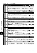
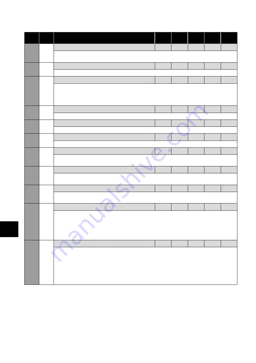
4.4.4. Group 4 Parameters & Modbus Registers
Par
Mod
Add Description
Def
Min
Max
Unit
R/W
4-01
401
PI Controller Proportional Gain
1
0.1
30.0
-
R/W
Higher values provide a greater change in the drive output frequency in response to small changes in the
feedback signal. Too high a value can cause instability.
4-02
402 PI Controller Integral Time
1
0.0
30.0
S
R/W
Larger values provide a more damped response for systems where the overall process responds slowly.
4-03
403 PI Operating Mode
0
0
1
-
R/W
0: Direct Operation.
Use this mode if a reduction in the feedback signal should result in an increase in the
motor speed.
1: Inverse Operation.
Use this mode if an increase in the feedback signal should result in an increase in the
motor speed.
4-04
404 PI Set-Point
0.0
0.0
100
%
R/W
This parameter sets the digital reference (setpoint) used for the PID Controller.
4-05
405 User PI Controller Output High Limit
100
P4-06
100
%
R/W
Limits the maximum value output from the PI controller.
4-06
406 User PI Controller Output Low Limit
0
0
P4-05
%
R/W
Limits the minimum output from the PI controller.
4-07
407 PI Error To Enable Ramps
0.0
0.0
25.0
%
R/W
Defines a threshold PI error level, whereby if the PI error is less than the set threshold, the internal ramps of the
drive are disabled.
4-08
408 PI Error Wake-Up Level
5.0
0.0
100
%
R/W
Sets an error level (difference between the PID reference and feedback values) above which the PID controller
will wake from Standby mode.
4-09
409 Standby Speed Threshold
0
0
P1-01
Rps
R/W
Specifies the speed boundary below which the drive enters Standby mode after the delay period P4-10. If the
speed increases above this threshold when the drive is in Standby mode, normal operation will be resumed.
4-10
410
Standby Mode Timer
0
0
6000
S
R/W
Enables the standby mode,
0: Standby mode disabled.
Non-zero: The drive will enter standby mode (output disabled) if the Standby Speed
Threshold (P4-09) is maintained for the time specified in this parameter.
Operation automatically resumes as soon as the PI Error increases above the value set in P4-08.
4-11
411
PI Reset Control
0
0
1
-
R/W
Selects whether the internal PI controller operates continuously, or is disabled when the drive stops. With
continuous operation, the PI function is always active, which can result in the PI controller reaching maximum
output whilst the drive is disabled. Resetting the PI controller on drive disable means the PI output will always start
from zero when the drive is enabled.
0: PI loop will run continuously as long as P gain (P4-01) is not zero.
1: PI loop will only run when the drive is enabled.
If the drive is not running, the PI output will be reset
to 0 (including the integral result).


