Version 2.04
| Optidrive ODP-2 Solar Pump User Guide |
63
www.invertekdrives.com
10. Serial Communications
10.1. RJ45 Connector Pin Assignment
The P2 Solar Pump drive has an RJ45 connector on the front of the control panel. This connector allows the user to set up a drive
network via a wired connection. The connector contains multiple interfaces for different communication protocols:
Invertek’s Optibus Protocol - Used for PC and peripheral connection only
Modbus RTU
BACnet MSTP
The Optibus connection is always
available, and can be used simultaneously
with other interfaces, however only one
other interface may be used, e.g. If
Modbus RTU is in use, BACnet is disabled.
If a Fieldbus Option Module (E.g. Profibus)
is inserted into the drive, both Modbus and
BACnet are disabled.
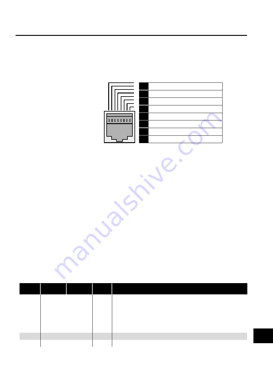
The electrical signal arrangement of the
RJ45 connector is shown as follows:
1
Not used
2
Not used
3
0 Volts
4
-RS485 (PC)
5
+RS485 (PC)
6
+24 Volt
7
-RS485 (Modbus RTU)
8
+RS485 (Modbus RTU)
Warning:
This is not an Ethernet connection. Do not connect directly to an Ethernet port. Ensure that an isolated comms channel is used on your
device or use a fully isolated communications convertor to connect to your PC.
Warning:
When using Modbus RTU or BACnet, ensure that the 0V signal (T3) is also used to avoid comms errors and potentially damaging
common mode voltages
10.2. Modbus RTU Communications
10.2.1. Modbus Telegram Structure
The Optidrive P2 Solar Pump Drive supports Master / Slave Modbus RTU communications, using the 03 Read Holding Registers, 06
Write Single Holding Register and for the first four registers only 16 Write Multiple Register commands. Many Master devices treat the
first Register address as Register 0; therefore it may be necessary to convert the Register Numbers detail (for the first four registers only)
in section 0 by subtracting 1 to obtain the correct Register address.
10.2.2. Modbus Control & Monitoring Registers
The following is a list of accessible Modbus Registers available in the Optidrive P2 Solar Pump Drive.
When Modbus RTU is configured as the Fieldbus option, all of the listed registers can be accessed.
Registers 1 and 2 can be used to control the drive providing that Modbus RTU is selected as the primary command source (P1-12
= 4) and no Fieldbus Option Module is installed in the drive Option Slot.
Register 4 can be used to control the acceleration and deceleration rate of the drive providing that Fieldbus Ramp Control is
enabled (P5-07 = 1).
Registers 6 to 24 can be read regardless of the setting of P1-12.
Register
Number Upper Byte Lower Byte
Read
Write
Notes
1
Command Control Word
R/W
Command control word used to control the Optidrive when operating with Modbus
RTU. The Control Word bit functions are as follows:
Bit 0 : Run/Stop command. Set to 1 to enable the drive. Set to 0 to stop the drive.
Bit 1 : Fast stop request. Set to 1 to enable drive to stop with 2nd deceleration ramp.
Bit 2 : Reset request. Set to 1 in order to reset any active faults or trips on the drive.
This bit must be reset to zero once the fault has been cleared.
Bit 3 : Coast stop request. Set to 1 to issue a coast stop command.
2
Command Speed Reference
R/W
Setpoint must be sent to the drive in Hz to one decimal place, e.g. 500 = 50.0Hz
3
Command Torque Reference
R/W
Setpoint must be sent to the drive in % to one decimal place, e.g. 2000 = 200.0%
Serial Communications
10


