56
| Optidrive ODP-2 Solar Pump User Guide |
Version 2.04
www.invertekdrives.com
Par
Name
Minimum
Maximum
Default
Units
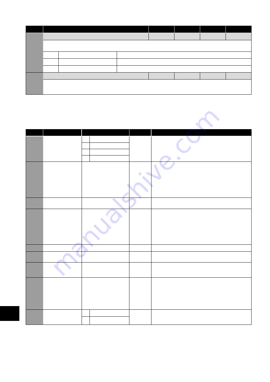
P5-14
Fieldbus PDI-3 Function Select
0
2
0
-
When using an optional Fieldbus interface, this parameter configures the parameter source for the 3rd process data word transferred
from the network master to the drive during cyclic communications:
0
Not used
No function
1
User Reference
0 to 1000 = 0% to 100.0%
2
User Register 3
Can be accessed by PLC program or group 9 parameters.
P5-15
Modbus Response Delay
0
16
0
Chr
Allows the user to configure an additional delay between the drive receiving a request via the Modbus RTU interface, and transmitting a
reply. The value entered represents the delay in addition to the minimum delay permissible according to the Modbus RTU specification,
and is expressed as the number of additional characters.
9.5. Advanced Parameters
For Advanced Parameters, basic information only is provided in this guide. The parameter functions are described more fully in
Optitools Studio PC software.
9.5.1. Parameter Group 6 – Advanced Configuration
Par.
Function
Setting Range
Default
Notes
P6-01
Enable Firmware
Upgrade
0
Disabled
0
This parameter should not be adjusted by the user.
1
I/O and DSP Upgrade
2
I/O Upgrade
3
DSP Upgrade
P6-02
Automatic Thermal
management
Minimum Effective
Switching Frequency
4 – 32kHz (Model
Dependent)
4 kHz
This parameter defines the minimum effective switching
frequency which the drive will use.
During operation, the drive measures the power module
temperature and will switch automatically to a lower switching
frequency if the temperature reaches a pre-defined limit. This
parameter determines the lowest frequency that can be used.
In the event that the power module temperature continues to
increase, the drive will trip on over temperature.
P6-03
Auto Reset Time Delay
1 – 60 Seconds
20s
Sets the delay time which will elapse between consecutive
drive reset attempts when Auto Reset is enabled in P2-36.
P6-04
Relay Output
Hysteresis
0.0 – 25.0%
0.3%
This parameter works in conjunction with P2-11 and P2-13 =
2 or 3 to set a band around the target speed (P2-11 = 2) or
zero speed (P2-11 = 3). When the speed is within this band, the
drive is considered to be at target speed or Zero speed. This
function is used to prevent “chatter” on the relay output if the
operating speed coincides with the level at which the digital /
relay output changes state. e.g. if P2-13 = 3, P1-01 = 50Hz
and P6-04 = 5%, the relay contacts close above 2.5Hz.
P6-05
MPPT Enable Mode
0 - 2
0
This parameter enables and disables the MPPT controller.
P6-06
Delay Start Time
0 - 30
0
This setting introduces a delay from when the drive is given a run
command to when the drive will start to run the motor.
P6-07
Delay Stop Time
0 - 30
0
This setting introduces a delay from when the drive is given a
stop command to when the drive will begin to stop the motor.
This value has no affect on the operation of the STO.
P6-08
Maximum Speed
Reference Frequency
0 – 20kHz
0 kHz
When the motor speed reference is to be controlled by
a frequency input signal (connected to Digital input 3),
this parameter is used to define the input frequency which
corresponds to the maximum motor speed (set in P1-01). This
maximum frequency that can be set in this parameter must be in
the range 5kHz to 20kHz.
When set to 0, this function is disabled.
P6-10
Function Block
Program Enable
0
Disabled
0
This parameter must be set to 1 to enable any Function Block
Program loaded into the drive to operate. When set to 0, the
Function Block Program will be disabled.
1
Enabled
9
Extended P
arameters


