18
INSTALLATION AND ASSEMBLY
18
iV-Light ventilation unit | Installation instructions
4.3 Laying the cables to the wall opening of the ventilation unit
DANGER
Exposed electrical components.
Electric shock and injury due to live components (230V, 50Hz)!
•
Before working on electrical installations, disconnect all affected equipment from the power
supply.
• Observe the requirements for protection class II when laying the power supply cable.
Do not lay and/or connect live cables.
• Lay the mains connecting cables and signal cables separately.
Installation and connection must only be performed by qualified and trained personnel.
Cable to the wall opening of the ventilation unit
The following cables, depending on the control unit, are laid to the wall opening for the ventilation
unit:
Use
Cable type
Cable origin
sMove
Operating voltage fan
and
unit communication
Stranded cable
6 – 16 V DC,
e. g.: LiYY 3x0.75 mm²
sMove operating unit
MZ-Home
Clust-Air module CAM17
in the ventilation zone
inVENTer
Connect
(Connect inner
cover)
Connect inner cover
operating voltage
Installation cable
230 V AC,
e. g.: NYM-J 3x1.5 mm²
House distribution,
ventilation
sub-distribution
Unit communication
(only if the system compo-
nents communicate by cable
[otherwise radio])
RS485 data cable,
e. g.:
Type J-Y(ST)Y 2x2x0.8 mm²
Easy Connect e16
operating unit
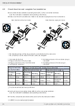
Once the wall opening has been created, the cables necessary for operating the ventilation
system are laid to the wall opening for the ventilation unit. They connect the valve gate of the
ventilation unit with the control components and thus establish signal transmission and/or
voltage transmission between the controller and the Xenion reversible fan.
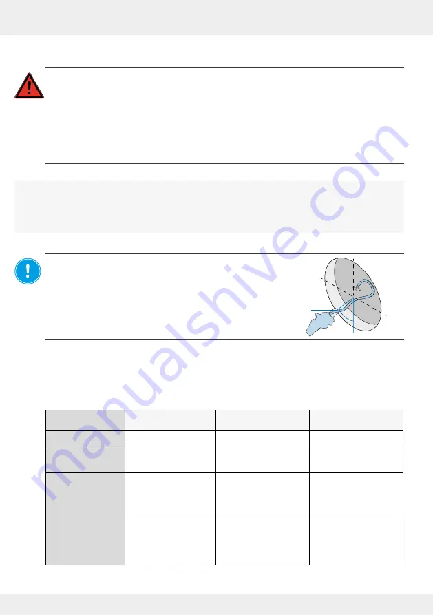
NOTICE: Cable to the wall opening of the ventilation unit not
laid.
No connection of the reversible fan possible!
Routing of the cables to the wall opening for the ventilation unit
must be done in this installation step. The routing of the connecting
cables to the Connect inner cover or between the sMove/ MZ-Home
controllers and the Xenion reversible fan is not part of this
documentation. For more information, see the installation
instructions for the corresponding controller.
45°
Содержание 1001-0200
Страница 1: ...www inventer de Installation instructions iV Light ...
Страница 37: ...37 WARRANTY AND GUARANTEE 37 iV Light ventilation unit Installation instructions NOTES ...
Страница 38: ...38 WARRANTY AND GUARANTEE 38 iV Light ventilation unit Installation instructions NOTES ...
Страница 39: ...39 WARRANTY AND GUARANTEE 39 iV Light ventilation unit Installation instructions NOTES ...


