


Select this preset from the list, click
Apply
in the Selected Preset group and then click
Test
. If the
shaft does not make a 360° turn you will have to adjust this parameter manually. Do experiment.
The 360° turn should be within the 205-235µs range.
Should you require a different angle, here are some Turn Offset values for reference:
- a Turn Offset of ~120 µs will result in a 180° turn,
- a Turn Offset of ~435 µs will result in two whole turns (720°).
3.2.2. Overcurrent Protection
Note:
do NOT change this parameter if you have no prior experience. Before changing this
parameter make sure you read and understand this chapter.
Fig. 15
Default overcurrent protection settings
The aim of overcurrent protection (
Fig. 11-A
) is to protect the drive and electronics from damage.
The motor draws high currents when:
a) the drive gets blocked – this usually happens when the camera hits the landing gear
during operation or something gets stuck between the pulleys and the belt,
b) the load is high and the driving parameters are too aggressive – a heavy camera is used
and the Acceleration and Max. Speed parameters (
Tab.2
) are too high for the load.
Pano360 electronics has the ability to detect high currents that are drawn by the servo in
the above scenarios.
If, during operation, the current value exceeds the Threshold and does not
drop below Threshold minus Hysteresis within the Time Limit then the motor will be turned off
and that should hopeful protect Pano360 from damage.
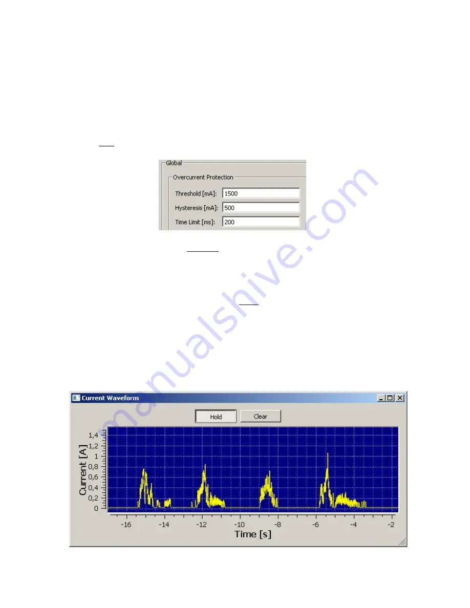
You can view the current waveforms by clinking
Current Waveform
at the GUI bottom.
Current waveform show how much current is drawn over time by the servo motor during
operation.
Fig. 16
Waveform example, Number of steps=4, Acc.:500, Dec:500, Max Speed:500, Load: 1.6 kg
Step 1
Step 2
Step 3
Step 4


