


3.1 Quick example on how to set the parameters in Pano360 GUI
To follow this example please make sure you have installed the software and everything is properly
connected (refer to:
2.1
,
2.2
,
2.3
should something be missing). If the micro USB cable or the
power supply (mini-T connector) are not connected the GUI will not be active. For this example we
will be triggering the camera by cable – make sure you have a matching cable and the cable
triggering is enable for your camera.
•
Load the GUI –
Start
→
All Programs
→
Invendyne Pano360
→
Configuration
•
Do not change Overcurrent Protection and Stop Detection parameters.
•
Leave Servo Pulse parameters (Home Location and Turn offset) for now, the default values
might not be ideal but they should be pretty close.
•
Select
Default 1
in the Preset list (
Fig. 11-
D
).
Fig. 12
Choosing presets for editing from the preset list in Pano360 GUI
•
Set the values of
General, Kinematics
and
Camera Release
for the Selected Preset as
shown below
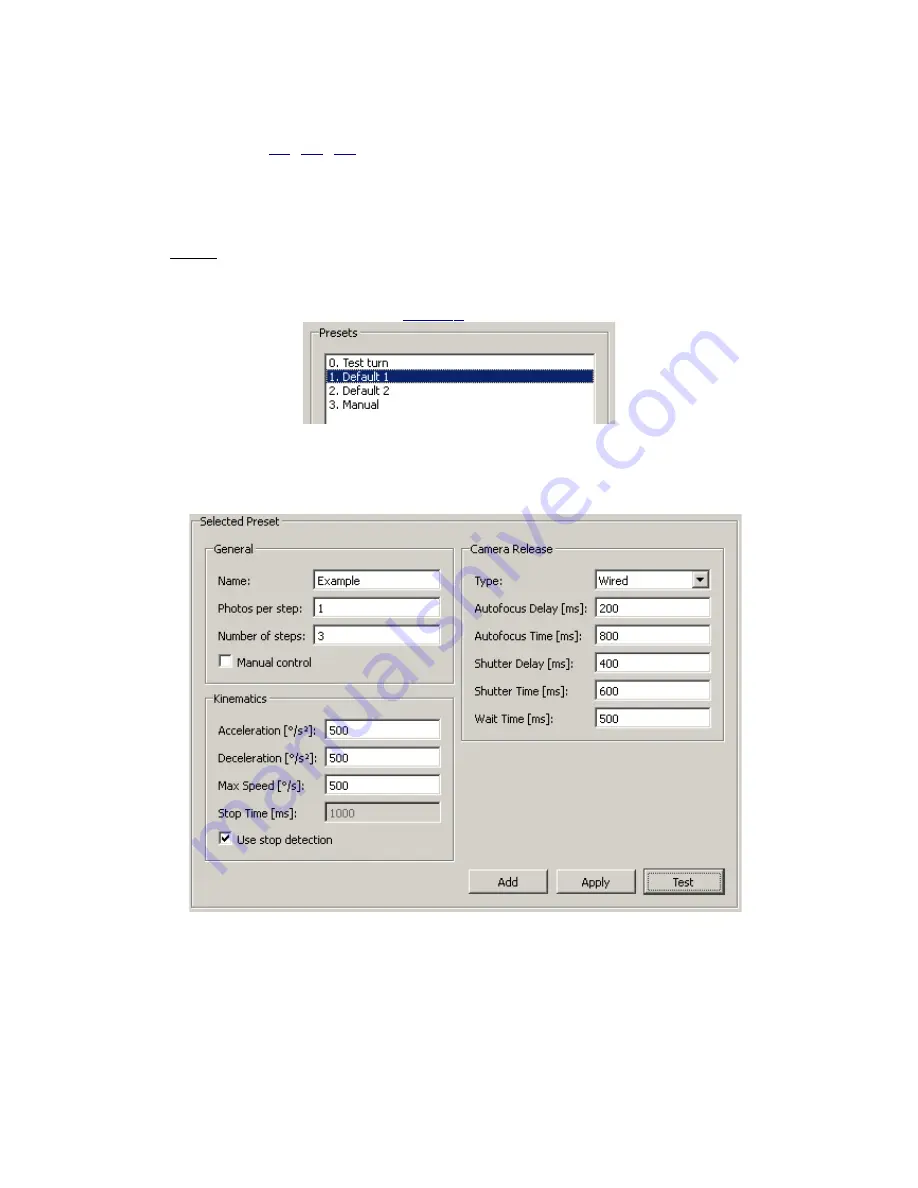
Fig. 13
A quick example on how to setup the Pano360 parameters.
•
Click the bottom
Apply
button in the Selected Preset Section, all the parameters are
instantly applied onto Pano360.
•
Now click
Test
and notice the results.
In this example we have configured Pano360 to trigger an automatic panorama
sequence that makes 1 photo per each turn (
Photos per step:1
). There are 3 turns with a roughly
120° angle (
Number of steps:3
). The rotation is made in a moderate speed (
Acceleration: 500,
Deceleration: 500, Max Speed: 500
).
Stop detection is active
to enable the driver to determine


