Page 36 of 83
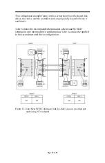
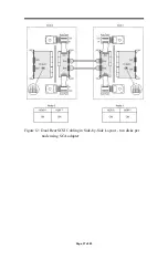
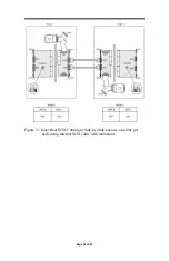
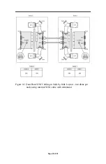
The configuration example figures in this section show how the shared disk
drives, the cables, and the controller cards are physically located in Node 0
and Node 1.
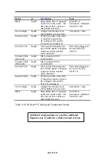
Table 6
shows the recommended termination scheme and SCSI ID
settings for one mirrored drive configuration.
Table 6
can also be applied
to the second mirrored drive configuration.
Figure 11: Dual Rear SCSI Cabling in Side-by-Side Layout - one disk per
node using SCA adapter
Содержание ITI-8001
Страница 8: ...Page 8 of 83 END USER LICENSE AGREEMENT FOR SOFTWARE 77 PRODUCT WARRANTY 81 READER S COMMENTS 83 ...
Страница 30: ...Page 30 of 83 LVD bus segment The adapter will terminate the other end of the bus automatically ...
Страница 37: ...Page 37 of 83 Figure 12 Dual Rear SCSI Cabling in Side by Side Layout two disks per node using SCA adapter ...
Страница 69: ...Page 69 of 83 Wide SCSI 16 Bit SCSI Table 8 Glossary of Terms ...

