


International Communications Group, Inc.
User’s Guide and Installation Manual
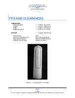
Sigma
7
Aviation Telephone Handset
Sigma
7
13
April 2006
Use or disclosure of information on this page is subject to the restrictions in the proprietary notice of this document.
INSTALLATION PROCEDURES
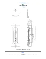
1. Planning
The ICG Sigma
7
is easy to install and test. However, both advance planning and review of this
document are recommended before an installation. A regular toolkit is sufficient for attaching all
hardware to the aircraft.
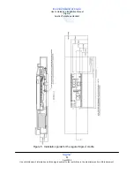
2. Connections
The 2-wire Sigma
7
telephone has a Printed Circuit Board (PCB) with three RJ-11 jacks, an 8-Pin
connector, located on the under side of the cradle, and an RJ-11 jack inside the cradle (optional).
The 4-wire Sigma
7
is fitted with a cable assembly terminated with a DB-15 male connector. The
RJ-11 jacks in the 2-wire phone and the DB-15 connector in the 4-wire phone are used for all
connections to the handset. The jacks are labeled J1, J2, J3, J4, and J5. Connections are as
follows:
J1 – Telephone Line
J2 – Retractor Reel Handset Connection
J3 – External Ringer Connection
J4 – 8-Pin Header for connection for LAN system
J5 – Currently, RJ-11 for Data Modem Connection.
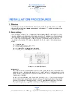
Figure 3. RJ interconnection
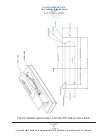
(A) Line (J1)
This is the connection to the telephone circuit of a CTU system, transceiver, or other telephone
subscriber circuit. The center two pins of the RJ-11 jack (Pins 3 and 4) are the telephone circuit
for the handset. The adjacent two pins (Pins 2 and 5) can be used for a separate connection for
the data jack, if installed.
An RJ-11 jack can have four or six contact pins. In a four-pin RJ-11 jack, the first and last pins
are not installed (pins at each end). However, although the pins may be absent, they are still
counted in the standard numbering scheme. An RJ-11 jack has pins designated 1 through 6.
The center two pins are always Pins 3 and 4 even if Pins 1 and 6 are not installed
Содержание Sigma7
Страница 2: ......