21
2. INSTALLATION
2.1 Hardware Descriptions
The Managed Switch provides four different running speeds – 10Mbps, 100Mbps, 1000Mbps and 10Gbps in the same Switch and
automatically distinguishes the speed of incoming connection. This section describes the hardware features of Managed Switch.
For easier management and control of the Managed Switch, familiarize yourself with its display indicators and ports. Front panel
illustrations in this chapter display the unit LED indicators. Before connecting any network device to the Managed Switch, read this
chapter carefully.
2.1.1 Front Panel
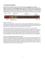
Figure 2-1
shows the front panel of
Managed Switch
.
Figure 2-1: NS4750-24S-4T-4X
Switch Front Panel
■
Gigabit TP interface
10/100/1000Base-T Copper, RJ-45 Twist-Pair: Up to 100 meters.
■
Gigabit SFP slots
1000Base-SX/LX mini-GBIC slot, SFP (Small Factor Pluggable) Transceiver Module supports from 550 meters (Multi-mode
Fiber), up to 10/30/50/70/120 kilometers (Single Mode Fiber).
■
10 Gigabit SFP slots
10GBase-SR/LR mini-GBIC slot, SFP (Small Factor Pluggable) Transceiver Module supports from 300 meters (Multi-mode
Fiber), up to 10 kilometers (Single Mode Fiber)
■
Console Port
The console port is a RJ-45 port connector. It is an interface for connecting a terminal directly. Through the console port, it
provides rich diagnostic information including IP address setting, factory reset, port management, link status and system
setting. Users can use the attached DB9 to RJ-45 console cable in the package and connect to the console port on the device.
After the connection, users can run any terminal emulation program (Hyper Terminal, ProComm Plus, Telix, Winterm and so
on) to enter the startup screen of the device.
Содержание NS4750-24S-4T-4X
Страница 1: ...NS4750 24S 4T 4X User Manual P N 1702826 REV 00 01 ISS 14JUL14 ...
Страница 56: ...56 Figure 4 2 7 Privilege Levels Configuration Page Screenshot ...
Страница 110: ...110 Figure 4 4 6 Mirror Configuration Page Screenshot ...
Страница 117: ...117 Figure 4 5 4 LACP Port Configuration Page Screenshot ...
Страница 136: ...136 Figure 4 6 5 VLAN Port Status for Static User Page Screenshot The Page includes the following fields ...
Страница 144: ...144 Figure 4 6 10 Change Port VLAN of Port 1 3 to be VLAN2 and Port VLAN of Port 4 6 to be VLAN3 ...
Страница 174: ...174 Figure 4 7 10 MST1 MSTI Port Configuration Page Screenshot ...
Страница 180: ...180 Figure 4 8 2 Multicast Flooding ...
Страница 249: ...249 Figure 4 9 18 Voice VLAN Configuration Page Screenshot ...
Страница 271: ...271 Counter Counts the number of frames that match this ACE ...
Страница 281: ...281 Figure 4 11 4 Network Access Server Configuration Page Screenshot ...
Страница 315: ...315 ...
Страница 328: ...328 ...
Страница 335: ...335 ...
Страница 346: ...346 Figure 4 14 1 LLDP Configuration Page Screenshot ...
Страница 350: ...350 Figure 4 14 2 LLDP MED Configuration Page Screenshot ...
Страница 372: ...372 Figure 4 16 1 Loop Protection Configuration Page Screenshot ...
Страница 377: ...377 Falling Threshold Falling threshold value 2147483648 2147483647 Falling Index Falling event index 1 65535 ...


