background image


47 

5  Installing the System in a Rack 

The SR2100 system comes with a rail kit that allows you to install it into a four-post, network 
server cabinet (e.g. APC Netshelter).  If the cabinet is not of this general type, you will have to 
purchase a separate rail kit that is specific to your cabinet. 

Follow these steps to install the rail kit and place your system into the cabinet. 

1.  Assemble tools and miscellaneous parts.  You will need a Phillips screwdriver and assorted 

lock washers and nuts. 

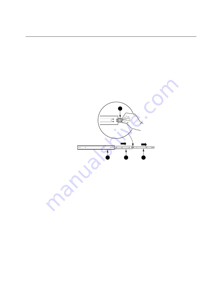
2.  Remove the inside piece (Figure 29, C) from both sides of the rail system.  

To remove an inside piece of the rail system, slide the part as far out as you can.  This action 
reveals a brass colored finger tab (D) that when depressed allows you to completely separate 
the inside rail piece from the outer (A) and middle (B) rail pieces. 

OM09132

A

B

C

D


Figure 29.  Chassis Rail System 

Содержание SR2100

Страница 1: ...uide for Technically Qualified Assemblers of Intel Identified Subassemblies Products Order Number A45510 002 Translations can be found on the accompanying CD ROM and at the following URL http support intel com support motherboards server chassis sr2100 ...

Страница 2: ...of any patent copyright or other intellectual property right Intel products are not designed intended or authorized for use in any medical life saving or life sustaining applications or for any other application in which the failure of the Intel product could create a situation where personal injury or death may occur Intel may make changes to specifications and product descriptions at any time wi...

Страница 3: ... You Begin 19 Tools and Supplies Needed 19 Installation Assembly Safety Instructions 19 Use Only for Intended Applications 20 Checking the Power Cords 20 Warnings and Cautions 21 Lithium Battery Replacement 22 Equipment Rack Precaution Information 23 Equipment Rack Precautions 23 Installing the Server Board 24 Removing the Cover 24 Installing the Server Board 25 Installing the Speaker 28 Cabling t...

Страница 4: ...cing the Power Supply 68 A Regulatory and Certification Information Product Regulatory Compliance 71 Product Safety Compliance 71 Product EMC Compliance 72 Product Regulatory Compliance Markings 72 Electromagnetic Compatibility Notices 73 FCC Verification Statement USA 73 ICES 003 Canada 74 Europe CE Declaration of Conformity 74 VCCI Japan 74 BSMI Taiwan 75 Regulated Specified Components 75 B Equi...

Страница 5: ...lling the Riser Card 33 16 Removing the Riser Card Assembly from the Server Board 34 17 Installing a PCI Add in Card in the Riser Card 35 18 Using the Add in Card Guide 36 19 Reinstalling the Riser Card 37 20 Removing a Hard Drive Carrier from a Drive Bay 38 21 Removing an Air Baffle 38 22 Attaching the Drive to the Carrier 39 23 Attaching a Slim line CD ROM Drive to the CD ROM Tray 40 24 Installi...

Страница 6: ...acing the Front Panel Board 57 47 Disconnecting the Hot Swap Backplane 58 48 Removing the Hot Swap Bay 59 49 Removing the Hot Swap Backplane 60 50 Reinstalling the Hot Swap Bay 61 51 Replacing a Fan 62 52 Removing the CD ROM Drive 63 53 Removing a CD ROM Drive from the CD ROM Tray 64 54 Installing a CD ROM Drive 65 55 Replacing a Power Supply Module 67 56 Replacing the Power Supply 68 Tables 1 Pow...

Страница 7: ...s with drive blanks baffles Two hot swappable 1 6 inch SCSI hard drive carriers with drive blanks baffles Ultra2 Ultra160 SCSI backplane with SAF TE supporting up to 4 SCA drives One empty 3 5 inch drive bay which supports either a standard floppy a 1 inch drive or other half height peripheral Cables One power cord U S version Ultra2 Ultra160 SCSI cable non terminated for baseboard to backplane co...

Страница 8: ...8 Intel SR2100 Chassis Subassembly Product Guide ...

Страница 9: ...assis The major component of the kit is the chassis which comes pre assembled with the exception of the server board and optional peripherals Before adding these devices it is important to become familiar with the chassis both externally and internally and the security features it provides NOTE The following sections provide a high level overview of the chassis For a more detailed technical descri...

Страница 10: ...t towards you OM11044 A B C D E F A 3 5 inch peripheral bay D 1 inch hot swap drive bay up to 2 drives B Control panel E Bezel lock C 1 6 inch hot swap drive bay up to 2 drives F Slim line device bay Figure 1 Front View of the SR2100 For a description of the control panel and its controls and indicators refer to Using the Front Panel Controls and Indicators on page 16 ...

Страница 11: ...onnector Com1 J RJ45 Network connector C Knockout optional external SCSI connector K Video connector D Parallel Port connector L Mouse connector E PCI expansion slots M Keyboard connector F AC input power connector N NMI switch G Cover empty power supply bay O Serial port connector Com2 H Power supply Figure 2 Back View of the SR2100 ...

Страница 12: ... H Hard drives up to four B PCI expansion slots I EMI shield C Riser card assembly J Control panel D Intrusion switch K CD ROM drive bay E Server board accessory to system L Bay assembly for 3 5 inch drives F Fan assembly M Hot swap backplane G Hot swap peripheral bay Figure 3 Major Internal Components of SR2100 ...

Страница 13: ...he chassis includes two system fans for cooling and airflow Both fans provide cooling for the processor s hard drives and add in cards The power supply contains its own built in fan for cooling As shown in Figure 3 two 80mm fans are located in the middle of the chassis to pull cooling air through the chassis Security To help prevent unauthorized entry or use of the system the chassis includes a me...

Страница 14: ...the bay Either four 1 inch high or two 1 inch high and two 1 6 inch high 3 5 inch SCA compatible SCSI hard drives can be installed in the bay Drives can consume up to 17 watts of power each Drives must be specified to run at a maximum ambient temperature of 50 C The chassis ships with four drive carriers for mounting the separately purchased hard drives For information on how to install these driv...

Страница 15: ...ezel do the following 1 Stand in front of the chassis and grasp the edges of the bezel from each side 2 Gently pull the bezel towards you until it begins to separate from the chassis 3 As the bezel separates from the chassis allow it to swing to its open position situated below the chassis OM11055 Figure 4 Opening the Bezel 4 To close the bezel gently raise it upwards The hinging mechanism will gu...

Страница 16: ... quarter turn The bezel is now locked and cannot be opened To unlock the bezel insert the key into the lock and turn the lock clockwise until it stops about a quarter turn The bezel is now unlocked and can be opened again Using the Front Panel Controls and Indicators OM11058 A B E G F H D C A Power button E Power LED B Sleep button F NIC activity LED C Reset button G Fail LED D NMI button H Disk a...

Страница 17: ...and allows you to issue a non maskable interrupt After issuing the interrupt a memory dump can be performed to determine the cause of the problem The control panel LEDs report the following status Power LED When lit indicates that the system has power applied to it NIC activity LED When lit indicates activity between the system and the network to which it is connected Fail LED When lit indicates a...

Страница 18: ...18 Intel SR2100 Chassis Subassembly Product Guide ...

Страница 19: ...ght tools available to you and you will need to make sure you follow certain basic safety precautions Tools and Supplies Needed Before beginning your work make sure you have the following tools and supplies available Phillips cross head screwdriver 2 bit Anti static wrist strap recommended SR2100 subassembly kit Server board kit Processors and memory you purchased separately to add to the server b...

Страница 20: ...dify or use the supplied AC power cord s if it is not the exact type required The power supply cords are the main disconnect device to mains AC power The socket outlet shall be installed near the equipment and shall be readily accessible If the power cord s supplied with the system is not compatible with the AC wall outlet in your region get one that meets the following criteria The cord must be r...

Страница 21: ...ports on the back of the chassis 4 Provide some electrostatic discharge ESD protection by wearing an antistatic wrist strap attached to chassis ground any unpainted metal surface when handling components WARNING The power button on the front panel DOES NOT turn off the AC power To remove power from server you must unplug the AC power cord s from the wall outlet or the chassis WARNING Hazardous ele...

Страница 22: ...e manufacturer Dispose of used batteries according to the manufacturer s instructions ADVARSEL Lithiumbatteri Eksplosionsfare ved fejlagtig håndtering Udskiftning må kun ske med batteri af samme fabrikat og type Levér det brugte batteri tilbage til leverandøren ADVARSEL Lithiumbatteri Eksplosjonsfare Ved utskifting benyttes kun batteri som anbefalt av apparatfabrikanten Brukt batteri returneres ap...

Страница 23: ...proper grounding for the rack itself If server power cords are plugged into wall AC outlets the safety grounding conductor in each power cord provides proper grounding only for the server You must provide additional proper grounding for the rack and other devices installed in it OVER CURRENT PROTECTION The server is designed for an AC line voltage source with up to 20 amperes of over current prote...

Страница 24: ...d in the chassis 4 Cabling the server board to the other chassis components 5 Adding processors and memory to the server board 6 Installing PCI cards riser card and bracket 7 Replacing the cover Removing the Cover 1 Unscrew the two captive thumbscrews on the rear of the system 2 Pull the cover back and remove it from the chassis 3 Set the chassis cover aside and away from immediate work area OM110...

Страница 25: ...umbscrews on the rear retention bracket that hold the riser card mounting bracket in the chassis 2 Remove the riser card mounting bracket from the chassis to give you full access to the server board area See Figure 7 OM11137 Figure 7 Removing the Riser Card Mounting Bracket ...

Страница 26: ...the cutouts will align with the corresponding I O connectors on the server board See Figure 8 5 Make sure the metal fingers are on the inside of the chassis and snap the I O shield into place OM11053 A B Figure 8 Installing the I O Shield 6 Orient the board so that the I O connectors on the board are positioned in front of the I O shield 7 Insert the I O connectors into the I O shield and lay the ...

Страница 27: ...h shoulders are inserted into their matching holes on the board Figure 9 A 9 Mount the board to the chassis by installing the screws supplied with the chassis through the holes on the server board and into the threaded standoffs OM11046 A A Figure 9 Mounting the STL2 Server Board ...

Страница 28: ... B 2 Position the speaker and bracket on the chassis standoff C 3 Insert and tighten screw D to hold the bracket to the chassis The screw also holds the speaker to the bracket 4 Connect the cable to the server board at E Be careful not to pull the cable off of the speaker OM11049 D E A B C Figure 10 Installing the Speaker ...

Страница 29: ...e 11 Connecting Cables to the Front Panel Board 1 Ensure that the I2C cable from the hot swap backplane is connected at Figure 11 A CAUTION Do not use the cable shipped with the chassis for connection to B Only use the cable shipped with the server board 2 Connect the cable from the server board to the bottom connector B of the front panel board 3 If you are installing a diskette drive connect the...

Страница 30: ... optimal performance complying with FCC A the hot swap backplane SCSI cable should be routed as shown in the illustration below Folding the cable as shown in the illustration before connecting it to the system makes routing easier OM11042 Figure 12 Routing for the SCSI Cable ...

Страница 31: ...f the chassis to connector FAN3A Connect the power cables for the fan nearest the center of the chassis to connector FAN2A 3 Connect the front panel cable to the connector E 4 If you are installing a CD ROM connect the IDE cable to the connector H 5 If you are installing a diskette drive connect the diskette drive cable to the connector C 6 Connect the SCSI connector from the hot swap backplane ca...

Страница 32: ... Add In Cards on page 34 3 Place the riser card assembly on the appropriate server board slots Figure 15 Ensure that the rear retention bracket is centered on the opening in the rear of the chassis and that the riser card connectors are aligned with the corresponding server board slots CAUTION Press only on the riser card bracket and or the standoffs Do not press on the 64 bit connector or the ora...

Страница 33: ...over Once the server board and its components are installed you are done assembling the system unless you have optional peripherals or add in cards you wish to install If you need to install these components continue on to the next section Otherwise reattach the cover and continue on to Chapter 4 which describes how to install the system in a cabinet To reattach the cover 1 Place the cover on the ...

Страница 34: ...e system s riser card Add In Cards You can only add two PCI cards to this server You must use the PCI slots on the riser card and cannot use any expansion slots on the server board NOTE Most PCI add in cards must be installed when the riser card is removed from the chassis due to limited space between the riser card and the power supply To install an add in card 1 Remove the chassis cover if the c...

Страница 35: ... the retention bracket 6 Remove the add in board from its protective wrapper Set jumpers or switches according to the manufacturer s instructions OM11138 A F B C E D Figure 17 Installing a PCI Add in Card in the Riser Card 7 Insert the connector of the PCI card C into the appropriate open expansion slot on the riser card B Insure the tapered foot of the board retaining bracket is inserted into the...

Страница 36: ...ide see Figure 18 To do this pull arm A out enough to release the card guide Slide the guide from position C to position B in front of the fans Also you must remove the add in card extension from the end of the full length PCI card the card will not fit in the system with the extension still attached A B OM11136 C Figure 18 Using the Add in Card Guide ...

Страница 37: ...e 64 bit connector or the orange flexible circuit attached to the standoffs 11 Press the riser card firmly into the server board slots 12 Ensure that the tab on the riser card bracket is inserted in the slot of the bracket on the fan housing NOTE If you are installing a riser card containing a full length PCI card slide the card guide back to position C The card guide should now be holding the edg...

Страница 38: ... lever toward you until the tab end Figure 20 B of the lever is free of the housing slot A Pull the drive forward and out of the housing OM09653 B A Figure 20 Removing a Hard Drive Carrier from a Drive Bay 2 Release the air baffle Figure 21 A by removing the four screws B from the drive carrier drive slide track C 3 Remove the hard drive from its wrapper and place it on an anti static surface 4 Se...

Страница 39: ...e carrier slide track C insert the screws D that you previously removed and attach the carrier to the drive 7 Slide the carrier drive into the chassis with the retention mechanism extended in the open position and then push the arm towards the front of the chassis until the lever tab clicks into the chassis slot indicating that it is closed OM09654 C A E B D Figure 22 Attaching the Drive to the Ca...

Страница 40: ...D ROM the new device must be setup as the slave 1 Remove the drive from its protective wrapper and place it on an anti static surface 2 Set any jumpers and or switches on the drive according to the drive manufacturer s instructions 3 Attach the CD ROM drive to the CD ROM tray using the mounting screws Figure 23 A supplied with the system A OM09348 Figure 23 Attaching a Slim line CD ROM Drive to th...

Страница 41: ...nect the provided CD ROM IDE cable Figure 24 A and power cables B to the connectors at the back of the CD ROM 7 Insert the recessed retention screws C through the access holes in the top of the drive bay housing 8 Insert the retention screw D on the front of the chassis 9 Connect the CD ROM IDE cable to the server board See Figure 13 H on page 31 ...

Страница 42: ...ric procedure that for the purpose of example shows how to install a 3 5 inch hard drive 1 Remove the chassis cover if the chassis is not already open 2 Remove the EMI shield from the 3 5 inch drive bay opening by removing and saving the two mounting screws Figure 25 A 3 Slide the drive tray B out of the chassis OM11041 A B Figure 25 Removing the Drive Tray 4 Remove the 3 5 inch hard drive from it...

Страница 43: ... carrier through the front of the chassis being sure to insert the rear tab Figure 27 C on page 44 into its chassis slot and the two front tabs D into their chassis slots 8 Secure the drive tray and the EMI shield to the front of the chassis with the screws you removed earlier NOTE If you are installing a device that requires user access such as a diskette tape or zip drive do not reattach the EMI...

Страница 44: ...nnect the signal Figure 27 F and power E cables to the drive according to the manufacturer s specifications 10 Reattach the chassis cover if you have no other work to do within the chassis OM11048 B A E F C D Figure 27 Installing the Drive into the Chassis ...

Страница 45: ... filler panel Figure 28 A to release the latch 3 Rotate the handle down while pulling the filler panel toward you Pull the blank out and save it 4 Insert the second redundant power supply module in the bay 5 Grip the module handle rotate it down and push the module into the bay 6 When the module is nearly all of the way in the handle will rotate up At this time push firmly on the front of the hand...

Страница 46: ...46 Intel SR2100 Chassis Subassembly Product Guide ...

Страница 47: ...il kit and place your system into the cabinet 1 Assemble tools and miscellaneous parts You will need a Phillips screwdriver and assorted lock washers and nuts 2 Remove the inside piece Figure 29 C from both sides of the rail system To remove an inside piece of the rail system slide the part as far out as you can This action reveals a brass colored finger tab D that when depressed allows you to com...

Страница 48: ...and that the brass colored finger tab D is facing outward With the holes in the chassis C aligned with the holes in the rail fasten the rail using the smallest screws B supplied with the rail kit OM09133 A B C D Figure 30 Aligning Rail to Chassis Here is a combination side and rear view of the chassis after the right inside rail has been attached OM10121 Figure 31 Chassis Rear and Side View ...

Страница 49: ... bracket is facing up To attach a rail bracket use two flat head mounting screws Figure 33 A supplied with the kit to secure the bracket to the inside of the cabinet rack Fasten the screws by aligning the nutbar behind the bracket Be sure that the nutbar is positioned such that the isolated hole C is upright Tighten the screws A through the nutbar holes B Figure 33 shows how to align all pieces Th...

Страница 50: ...bracket Then put the nut on the backside of the rail bracket B OM09138 A C Figure 34 Attaching Outer Pieces to the Rail Brackets 7 To attach the rear part of the rail system to the rear rail bracket Figure 35 A slide the rail system within the rail brackets such that you can place a bolt through the rail s hole B and into the rail bracket s slot Tighten the bolt and nut A OM09144 B C Figure 35 Att...

Страница 51: ...t facing you and carefully guide the inner rail Figure 37 A that is mounted to the chassis system into the outer pieces B you attached in previous steps Gently move the system evenly towards the rear of the cabinet until it locks Press the brass colored finger tabs located in the center of each inner side rail piece to slide the chassis all the way back If you feel resistance as you slide the chas...

Страница 52: ...ct Guide 10 Be sure to use the largest screws to secure the chassis into the cabinet to keep the chassis from sliding out Figure 38 shows the system from the rear fully inserted into the cabinet OM10120 Figure 38 Chassis Mounted into the Rack ...

Страница 53: ...r Before removing the system cover to work inside the system observe these safety guidelines 1 Turn off all peripheral devices connected to the system 2 Turn off the system by pressing the power button on the front of the system Then unplug the AC power cord from the system or wall outlet 3 Label and disconnect all peripheral cables and all telecommunication lines connected to I O connectors or po...

Страница 54: ...OM11055 Figure 39 Opening the Bezel 2 Place your hands to the right and left of the bezel such that you can gently press each bezel hinge inward Pressing the hinges inward removes the hinge pegs from the bezel mounts See Figure 40 OM11056 A Figure 40 Removing Hinge Pegs from Bezel Mounts ...

Страница 55: ...he bezel mount 4 Remove the left bezel mount by removing the two screws from the back of the bezel mount OM11140 Figure 41 Removing a Bezel Mount 5 Locate the two new bezel mounts and the screws used to fasten them to the right and left sides of the front panel OM09186 Figure 42 Bezel Mounting Hardware ...

Страница 56: ...Attach the left bezel mount to the left side of the system in a manner similar to that described for the right bezel mount 8 Locate the bezel s left and right hinges Figure 44 A and extend them away from the bezel OM09731 A Figure 44 Extending the Bezel Hinges 9 Align the round pegs at the ends of the hinges with their respective holes in each bezel mount Figure 45 A Press inward on each hinge sli...

Страница 57: ...e front panel board OM10728 A B Figure 46 Replacing the Front Panel Board 4 Remove and save the two mounting screws Figure 46 B from the board Remove the board A from the chassis 5 Install the new board in the chassis using the two screws removed earlier 6 Plug the cables back into the front panel board 7 Replace the chassis cover if you have no additional work to do inside the chassis ...

Страница 58: ...Remove the cover from the chassis 4 Locate the backplane board Figure 47 A and the cables connected to it OM11142 A B C D A SCSI backplane B SCSI data cable C Power connector D Front panel connector Figure 47 Disconnecting the Hot Swap Backplane 5 Disconnect the SCSI data cable B from the backplane 6 Disconnect the power cable C from the backplane 7 Disconnect the front panel cable D from the back...

Страница 59: ...emoving the Hot Swap Bay 9 Remove and save the two screws B that hold the bay assembly to the front of the chassis 10 Slide the chassis out of the tabs on the bottom of the chassis and tilt the backplane side of the bay up and toward the front of the chassis C 11 Pull the bay out and clear of the chassis and set the front of bay on a flat working surface ...

Страница 60: ...emoving the Hot Swap Backplane 13 Remove the backplane from the bay and place it in an anti static bag 14 Remove the new backplane from its packaging 15 Orient the new board on the bay such that the locating pins on the bay B pass through the board 16 Attach the board to the bay using the six screws that you removed earlier 17 Position the bay back into the chassis ...

Страница 61: ...135 C D A B Figure 50 Reinstalling the Hot Swap Bay 19 Slide the bay into the tab located on the bottom front of the chassis B 20 Insert the interior and exterior screws that you removed earlier to reattach the bay to the chassis 21 Replace the chassis cover if you have no additional work to do inside the chassis ...

Страница 62: ...rd OM11144 A A B Figure 51 Replacing a Fan 4 Press the tabs Figure 51 A on both sides of the fan and lift it out of the fan assembly 5 Insert the new fan into the fan assembly making sure that the flow and rotation arrows on the fan point as shown in the figure B 6 Plug the fan cable back into the connector on the server board 7 Replace the chassis cover if you have no additional work to do inside...

Страница 63: ...access to the CD ROM drive 2 Remove the three screws holding the drive to the chassis Figure 52 C and D 3 Disconnect the data A and power B cables from the drive 4 Slide the drive tray out of the front of the chassis OM11145 D A B C A Data cable C Screws B Power cable D Retention screw Figure 52 Removing the CD ROM Drive ...

Страница 64: ...talling the same drive A OM09658 A Mounting screws Figure 53 Removing a CD ROM Drive from the CD ROM Tray 7 Remove the new drive from its protective wrapper and place it on an anti static surface 8 Set any jumpers and or switches on the drive according to the drive manufacturer s instructions 9 Attach the CD ROM drive to the CD ROM tray using the mounting screws Figure 53 A supplied with the syste...

Страница 65: ...DE cable and power cables Figure 54 A and B to the connector at the back of the CD ROM drive 12 Insert the recessed retention screws Figure 54 C through the access holes in the top of the drive bay housing 13 Insert the retention screw Figure 54 D on the front of the chassis 14 If you removed a drive from the 3 5 inch drive bay to replace the CD ROM drive re install it ...

Страница 66: ...their ends aside and away from the server board 5 Remove any processors and memory cards that you wish to use with the new board 6 Remove the mounting screws that secure the server board to the chassis 7 Place the server board in an anti static bag 8 Remove the new server board from its package 9 Mount the new server board to the chassis 10 Re cable the new server board to the chassis 11 Re instal...

Страница 67: ...Grip and squeeze the module handle Figure 55 to depress the latch that is the right side of the handle 2 Rotate the handle down while pulling the module toward you As you pull the module out support the module with your free hand 3 Insert a new power supply module in the bay 4 Grip the module handle rotate it down and push the module into the bay 5 When the module is nearly all of the way in the h...

Страница 68: ...er board hot swap backplane CD ROM drive and peripheral drives label and disconnect the power cables 6 Remove the power cables from the bundle clip located near the hot swap backplane power connector 7 Remove the wire tie from the server board power cables where they pass through the fan assembly 8 At the server disconnect both fans 9 Remove the two screws Figure 56 A that attach the fan assembly ...

Страница 69: ... the rear of the chassis and the one screw B at the fan end of the power supply 16 Place the power cables in the bundle clip 17 Place the fan assembly in the chassis Slide it away from the power supply and under the chassis clip Install two screws A and secure it to the chassis 18 At the server connect both fans 19 Install a new wire tie on the server board power cables where they pass through the...

Страница 70: ...70 Intel SR2100 Chassis Subassembly Product Guide ...

Страница 71: ...iance with product regulations in the region s in which the product is sold Product Regulatory Compliance The SR2100 chassis subassembly when correctly integrated per this guide complies with the following safety and electromagnetic compatibility EMC regulations NOTE Certifications for the SR2100 chassis may have been obtained under the name SR2100 and or the code BYRD2 Product Safety Compliance U...

Страница 72: ...iated Conducted Emissions Japan AS NZS 3548 Class A Radiated Conducted Emissions Australia RRL Class A Radiated Conducted Emissions Korea BSMI Class A Radiated Conducted Emissions Taiwan Product Regulatory Compliance Markings This product is provided with the following Product Certification Markings UL cUL Listing Mark CE Mark The CE marking on this product indicates that it is in compliance with ...

Страница 73: ...cular installation If this equipment does cause harmful interference to radio or television reception which can be determined by turning the equipment off and on the user is encouraged to try to correct the interference by one or more of the following measures Reorient or relocate the receiving antenna Increase the separation between the equipment and the receiver Connect the equipment into an out...

Страница 74: ...pment standard entitled Digital Apparatus ICES 003 of the Canadian Department of Communications Europe CE Declaration of Conformity This product has been tested in accordance too and complies with the Low Voltage Directive 73 23 EEC and EMC Directive 89 336 EEC The product has been marked with the CE Mark to illustrate its compliance VCCI Japan English translation of the notice above This is a Cla...

Страница 75: ... SR2100 chassis base chassis is provided with power supply and fans UL listed Server board you must use an Intel Server Board UL Recognized Add in boards must have a printed wiring board flammability rating of minimum UL94V 1 Add in boards containing external power connectors and or lithium batteries must be UL Recognized or UL Listed Any add in board containing modem telecommunication circuitry m...

Страница 76: ...76 Intel SR2100 Chassis Subassembly Product Guide ...

Страница 77: ...em You will need some of this information when you run the SSU Item Manufacturer Name and Model Number Serial Number Date Installed Chassis Server board Processor speed and cache Video display Video Controller Keyboard Mouse 3 5 drive CD ROM drive Hard disk drive 1 Hard disk drive 2 Hard disk drive 3 Hard disk drive 4 continued ...

Страница 78: ...78 Intel SR2100 Chassis Subassembly Product Guide Equipment Log continued Item Manufacturer Name and Model Number Serial Number Date Installed ...

Страница 79: ...nts Worksheet Calculating DC Power Usage 1 List the current for each board and device in the appropriate voltage level column 2 Add the currents in each column Then go to the next worksheet Table 1 Power Usage Worksheet 1 Current maximum at voltage level Device 5Vsb 3 3 V 5 V 5 V 12 V 12 V Boards processors and memory get totals from your board manual SCSI backplane Front panel board 3 5 inch driv...

Страница 80: ...arrive at a total combined power usage on the power supply Table 2 Power Usage Worksheet 2 Voltage level and total current V X A W Total Watts for each voltage level 5 Vsb X ______ A ________ W 3 3 V X ______ A ________ W 5 V X ______ A ________ W 5 V X ______ A ________ W 12 V X ______ A ________ W 12 V X ______ A ________ W Total Combined Wattage ________ W CAUTION Do not overload As an overall ...

Страница 81: ...81 C Safety Warnings WARNING English US AVERTISSEMENT Français WARNUNG Deutsch AVVERTENZA Italiano ADVERTENCIAS Español ...

Страница 82: ...ear the equipment and shall be easily accessible SAFETY STEPS Whenever you remove the chassis covers to access the inside of the system follow these steps 1 Turn off all peripheral devices connected to the system 2 Turn off the system by pressing the power button 3 Unplug all AC power cords from the system or from wall outlets 4 Label and disconnect all cables connected to I O connectors or ports ...

Страница 83: ...ts Contact should be made with care Consider wearing protective gloves Danger of explosion if the battery is incorrectly replaced Replace only with the same or equivalent type recommended by the equipment manufacturer Dispose of used batteries according to manufacturer s instructions The system is designed to operate in a typical office environment Choose a site that is Clean and free of airborne ...

Страница 84: ...der à l intérieur du système suivez les consignes suivantes 1 Mettez hors tension tous les périphériques connectés au système 2 Mettez le système hors tension en mettant l interrupteur général en position OFF bouton poussoir 3 Débranchez tous les cordons d alimentation c a du système et des prises murales 4 Identifiez et débranchez tous les câbles reliés aux connecteurs d E S ou aux accès derrière...

Страница 85: ...broches aiguës des cartes et aux bords tranchants du capot Nous vous recommandons l usage de gants de protection Danger d explosion si la batterie n est pas remontée correctement Remplacer uniquement avec une batterie du même type ou d un type équivalent recommandé par le fabricant Disposez des piles usées selon les instructions du fabricant Le système a été conçu pour fonctionner dans un cadre de...

Страница 86: ...um an das Systeminnere zu gelangen sollten Sie folgende Schritte beachten 1 Schalten Sie alle an Ihr System angeschlossenen Peripheriegeräte aus 2 Schalten Sie das System mit dem Hauptschalter aus 3 Ziehen Sie den Stromanschlußstecker Ihres Systems aus der Steckdose 4 Auf der Rückseite des Systems beschriften und ziehen Sie alle Anschlußkabel von den I O Anschlüssen oder Ports ab 5 Tragen Sie ein ...

Страница 87: ... scharfe Spitzen und Kanten aufweisen Arbeiten an Platinen und Gehäuse sollten vorsichtig ausgeführt werden Sie sollten Schutzhandschuhe tragen Bei falschem Einsetzen einer neuen Batterie besteht Explosionsgefahr Die Batterie darf nur durch denselben oder einen entsprechenden vom Hersteller empfohlenen Batterietyp ersetzt werden Entsorgen Sie verbrauchte Batterien den Anweisungen des Herstellers e...

Страница 88: ...edere all interno del sistema seguire i seguenti passi 1 Spegnere tutti i dispositivi periferici collegati al sistema 2 Spegnere il sistema usando il pulsante spento acceso dell interruttore del sistema 3 Togliere tutte le spine dei cavi del sistema dalle prese elettriche 4 Identificare e sconnettere tutti i cavi attaccati ai collegamenti I O od alle prese installate sul retro del sistema 5 Qualor...

Страница 89: ...i Fare attenzione alla presenza di piedini appuntiti e parti taglienti sulle schede e sul telaio È consigliabile l uso di guanti di protezione Esiste il pericolo di un esplosione se la pila non viene sostituita in modo corretto Utilizzare solo pile uguali o di tipo equivalente a quelle consigliate dal produttore Per disfarsi delle pile usate seguire le istruzioni del produttore Il sistema è proget...

Страница 90: ...ga la tapa del chasis para acceder al interior del sistema siga las siguientes instrucciones 1 Apague todos los dispositivos periféricos conectados al sistema 2 Apague el sistema presionando el interruptor encendido apagado 3 Desconecte todos los cables de alimentación CA del sistema o de las tomas de corriente alterna 4 Identifique y desconecte todos los cables enchufados a los conectores E S o a...

Страница 91: ...ner en cuenta que en el chasis o en el tablero puede haber piezas cortantes o punzantes Por ello se recomienda precaución y el uso de guantes protectores Existe peligro de explosión si la pila no se cambia de forma adecuada Utilice solamente pilas iguales o del mismo tipo que las recomendadas por el fabricante del equipo Para deshacerse de las pilas usadas siga igualmente las instrucciones del fab...

Страница 92: ...92 Intel SR2100 Chassis Subassembly Product Guide ...

Страница 93: ...able to repair or replace the Product If such Product is defective transportation charges for the return of Product to buyer within the USA will be paid by Intel For all other locations the warranty excludes all costs of shipping customs clearance and other related charges Intel will have a reasonable time to make repairs or to replace Product or to refund the then current value of the Product In ...

Страница 94: ...tial damages resulting from any breach of warranty under another legal theory including but not limited to lost profits downtime goodwill damage to or replacement of equipment and property and any costs of recovering reprogramming or reproducing any program or data stored in or used with a system containing this product Some jurisdictions do not allow the exclusion or limitation of incidental or c...

Страница 95: ... rate plus applicable taxes In U S and Canada 1 800 404 2284 In Europe UK 0870 6072439 France 01 41 918529 Germany 069 9509 6099 Italy 02 696 33276 Spain 91 377 8166 Finland 9 693 79297 Denmark 38 487077 Norway 23 1620 50 Sweden 08 445 1251 Holland 020 487 4562 In Asia Pacific region Australia 1800 649931 Hong Kong 852 2 844 4456 Korea 822 767 2595 PRC 800 820 1100 Singapore 65 831 1311 Taiwan 2 2...

Страница 96: ...product call your authorized dealer distribution authority If the customer support group verifies that your product is defective you will receive a Return Material Authorization RMA number to place on the outer package of the product Intel can not accept any product without an RMA number on the package ...

Отзывы: