background image

12

Reference

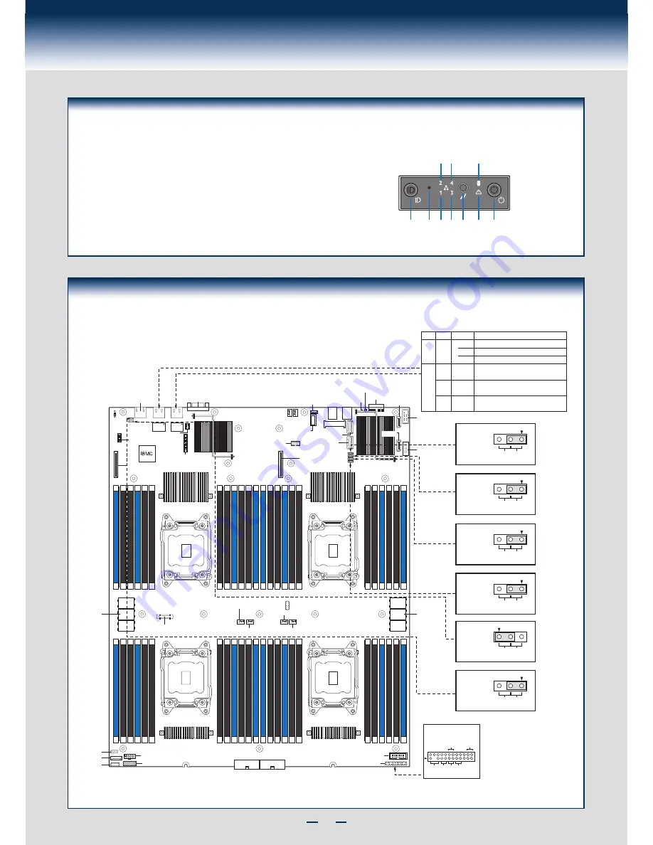
Front Panel Controls and Indicators

Standard Control Panel

H

I

J

A

B C D E F G

Your system may include one of two front control panel types.

The features of each are as follows:

A. ID Button with integrated LED
B. NMI Button
C. LAN-1 Activity LED
D. LAN-3 Activity LED
E. System Cold Reset Button

F. System Status LED
G. Power Button with integrated LED
H. HDD Activity LED
I. LAN-4 Activity LED
J. LAN-2 Activity LED

Intel® Server Board S4600LH2/LT2 Component Layout

See your 

Intel

®

 Server System R2000LH2/LT2 Service Guide

 for expanded component and connection information.

Serial A

Video

CPU 1 Socket

CPU 2 Socket

CPU 4 Socket

CPU 3 Socket

NIC2 NIC1

TPM Connector

I/O Expansion

Module Connector

I/O Expansion

Module Connector

RMM4 Lite

RMM4

NIC

eUSB SSD

Storage Upgrade Key

Internal USB

mSATA

USB USB

ID LED

Status

LED Diagnostic

LEDs

SCU0 (0-3)

SCU1 (4-7)

SATA 0

SATA 1

Serial B

USB

Riser 

Slot 1

Riser 

Slot 2

CPU Fan 3

CPU Fan 1

CPU Fan 4

CPU Fan 2

Front Panel

2

Reset

Button

NIC 2

Link/Act

NIC 1

Link/Act

Power

Button

HDD

LED

Power

LED

Front Panel Header

(J106)

Front Panel Video

Main Power 2

Main Power 1

IPMB

PDB Signal

LCP

HSBP I

2

C

Fan Board Power

3

2

Default

Password

Clear

3

2

Default

Password

Clear

3

2

Default

Password

Clear

J74

BIOS

Recovery

J75

BIOS

Default

3

2

Default

J73

Password

Clear

Password

Clear

J81

ME

Force

Update

3

2

DSR

(Default)

DCD

J33

Serial A

Jumper

3

2

Default Enabled

J37

BMC

Force

Update

DIMM_E1

DIMM_E2

DIMM_E3

DIMM_F1

DIMM_F2

DIMM_F3

DIMM_L1

DIMM_L2

DIMM_L3

DIMM_M1

DIMM_M2

DIMM_M3

DIMM_J1

DIMM_J2

DIMM_J3

DIMM_K1

DIMM_K2

DIMM_K3

DIMM_R1

DIMM_R2

DIMM_R3

DIMM_T1

DIMM_T2

DIMM_T3

DIMM_N1

DIMM_N2

DIMM_N3

DIMM_P1

DIMM_P2

DIMM_P3

DIMM_G1

DIMM_G2

DIMM_G3

DIMM_H1

DIMM_H2

DIMM_H3

DIMM_C1

DIMM_C2

DIMM_C3

DIMM_D1

DIMM_D2

DIMM_D3

DIMM_A1

DIMM_A2

DIMM_A3

DIMM_B1

DIMM_B2

DIMM_B3

LED

LED State NIC State

Right

100 Mbit/sec data rate is selected for S4600LT2.

Off

10 Mbit/sec data rate is selected for S4600LH2.

LAN activity is occurring.

Left

On

On

Blinking

LAN link is established.

Off

Color

N/A

Green

Green

Amber

LAN link is not established.

NIC LED Functions

On

10000 Mbit/sec data rate is selected for S4600LT2.

1000 Mbit/sec data rate is selected for S4600LH2.

1000 Mbit/sec data rate is selected for S4600LT2.

100 Mbit/sec data rate is selected for S4600LH2.

Battery

Содержание R2000LH2

Страница 1: ... If you are not familiar with ESD Electrostatic Discharge procedures used during system integration see the complete ESD procedures described in your Service Guide This guide and other supporting documents are located on the web at http www intel com support G54804 003 Intel Server System R2000LH2 LT2 Product Family Quick Installation User s Guide 3 5 hard drive bay system as shown ...

Страница 2: ... This page is intentionally left blank ...

Страница 3: ...k s 3 Install Processor s 3 Install Processor Heatsink s 4 Install Memory Modules 4 Install Hard Drives 5 Install Optical Drive 8 Install Intel I O Expansion Module optional 8 Install Intel RAID C600 Upgrade Key optional 8 Install Air Duct 9 Install Add in Card s 9 Install Add in Card Riser Assembly 10 Install Intel RAID Smart Battery optional 10 Install Top Cover 10 Install Power Supply Module 10...

Страница 4: ...stalled at all times with or without a processor installed Memory Slot population requirements NOTE Specified memory slots either can be populated with a DIMM or supplied DIMM Blank Memory population rules apply when installing DIMMs DIMM Population Rules on CPU 1 Install DIMMs in order Channels A B C and D Start with first DIMM slot blue on each channel then slot 2 then slot 3 Remove only DIMM bla...

Страница 5: ... Upgrade Key installed to be functional O p t i c a l D e v i c e A s s e m b l y Hard Drive Bays System Fans CPU2 CPU 3 Add in Card Riser Assembly 1 1 Redundant Power Supply Modules Server Board Air Duct Optical Drive Bay Front Control Panel CPU1 CPU4 System Features and Components A i r d u c t 3 5 Hard Drive Bay system as shown ...

Страница 6: ...cedures before reaching inside to make server board connections or install components CAUTION Unplug all AC power cords and remove all power supply modules before lifting tilt bay Lift up the tilt bay A Bend and slide out the air duct B Remove the air duct from the chassis C O p t i c a l D e v i c e A s s e m b l y A B B C 5 Remove Air Duct O p t i c a l D e v i c e A s s e m b l y B B A 3 Remove...

Страница 7: ...n the underside of it Use caution so that you do not damage the thermal interface material Use gloves to avoid sharp edges Using a 2 Phillips screwdriver loosen the four screws located on the heatsink corners in a diagonal manner using the following procedure Using a 2 Phillips screwdriver start with screw 1 and loosen it by giving it two rotations and stop IMPORTANT Do not fully loosen Proceed to...

Страница 8: ...ocket CPU 4 Socket CPU 3 Socket DIMM_E1 DIMM_E2 DIMM_E3 DIMM_F1 DIMM_F2 DIMM_F3 DIMM_L1 DIMM_L2 DIMM_L3 DIMM_M1 DIMM_M2 DIMM_M3 DIMM_J1 DIMM_J2 DIMM_J3 DIMM_K1 DIMM_K2 DIMM_K3 DIMM_R1 DIMM_R2 DIMM_R3 DIMM_T1 DIMM_T2 DIMM_T3 DIMM_N1 DIMM_N2 DIMM_N3 DIMM_P1 DIMM_P2 DIMM_P3 DIMM_G1 DIMM_G2 DIMM_G3 DIMM_H1 DIMM_H2 DIMM_H3 DIMM_C1 DIMM_C2 DIMM_C3 DIMM_D1 DIMM_D2 DIMM_D3 DIMM_A1 DIMM_A2 DIMM_A3 DIMM_B1 ...

Страница 9: ...only Hard Drive Numbering Diagram Drive 0 Primary 8 x 2 5 hard drive bay as shown A B Press the green latch to unlock Pull out the black lever and slide the carrier out D C Remove the four screws securing the plastic drive blank from the 2 5 HDD carrier Disengage the plastic drive blank from the HDD carrier Remove the plastic drive blank from the 2 5 HDD carrier C D Install the hard disk drive usi...

Страница 10: ...k drive using the same four screws as shown Make sure the connector end of the drive matches the backplane connector With the lever open insert the hard disk drive assembly into the chassis Push in the lever to lock it into place d1 Bottom View T O P B R E A K O F F T A B B E F O R E M O U T IN G 2 5 H A R D D R IV E d2 CAUTION If you don t install all drives empty drive bays must be occupied by c...

Страница 11: ...e Drive with the four screws C Slide the Solid State Drive carrier into the chassis D Secure the Solid State Drive carrier with the two screws E Connect the cables F Remove the six screws securing the front end module from the chassis A Slide the front end of the module forward a little B Push the front end module into place A Align the rack handle with the two holes on the side of the server syst...

Страница 12: ...server board connector NOTE If included remember to install the EMI shield B I O Module A C Install the module to the provided bracket Secure the module to the bracket with the three screws Install the provided connector converter Fix the I O Module to the Bracket before installing it at the left edge of the Board A B C 11 Install Optical Drive A B IMPORTANT NOTE If you do not install a device at ...

Страница 13: ...ON Observe normal ESD precautions when installing add in cards Remove the filler panel from the add in card slot and install the provided proper bracket as shown Insert add in card until it sits in the riser connector Secure add in card with screw provided with bracket as shown NOTE Make sure that all empty add in card slots have filler panels installed For Half length PCI Add in Card s For Full l...

Страница 14: ...e mounting holes A B O p t i c a l D e v i c e A s s e m b l y A C B 16 Install Add in Card Riser Assembly NOTE Please make sure the release lever is in UP position before installing the add in card riser assembly A Position the riser card connector edge over the server board riser socket and align the riser bracket to the plastic guides on the chassis Press down the release lever to install the r...

Страница 15: ...t the appropriate drivers to install On other operating systems browse the CD folders to locate and install the driver files Download the latest version of the Intel System Management Software from http www intel com content www us en server management intel server management html and use the instructions provided at that link to install the software NOTE The FRUSDR utility must be run for full pl...

Страница 16: ...t Panel Header J106 Front Panel Video Main Power 2 Main Power 1 IPMB PDB Signal LCP HSBP I2 C Fan Board Power 3 2 Default Password Clear 3 2 Default Password Clear 3 2 Default Password Clear J74 BIOS Recovery J75 BIOS Default 3 2 Default J73 Password Clear Password Clear J81 ME Force Update 3 2 DSR Default DCD J33 Serial A Jumper 3 2 Default Enabled J37 BMC Force Update DIMM_E1 DIMM_E2 DIMM_E3 DIM...

Страница 17: ...essories and spares can be found at http www intel com p en_US support O p t i c a l D e v i c e A s s e m b l y 11 10 9 8 AirFlow System Fan Connection System Fan Board FAN 7 FAN 6 FAN 5 FAN 4 FAN 3 FAN 2 FAN 1 FAN 9 FAN 8 FAN 11 FAN 10 ...

Страница 18: ...Front Panel Video Front Panel USB GPGPU GPGPU Intel Integrated RAID Module BBU RMFBU2 NOTES To activate the port SCU1 4 7 on the server board a proper Intel RAID C600 Upgrade Key must be installed For instructions see Intel RAID C600 Upgrade Key Installation Guide A second SSD is supported when the optical drive is NOT in use System Cabling Diagram For System with 4 x 3 5 Hard Drive Bay ...

Страница 19: ...st be installed For instructions see Intel RAID C600 Upgrade Key Installation Guide A second SSD is supported when the optical drive is NOT in use CPU4 Socket CPU3 Socket CPU1 Socket CPU2 Socket System Fan Board 8 x 2 5 HSBP Power Supply SSD SSD Optical Drive I 2 C HSBP_I2C Front Panel Front Panel Video Front Panel USB Intel Integrated RAID Module BBU RMFBU2 GPGPU GPGPU ...

Страница 20: ...G54804 003 ...

Отзывы: