


System Assumptions
Intel® Quark™ SE Microcontroller C1000
June 2017
Platform Design Guide
Document Number: 334715-004EN
13
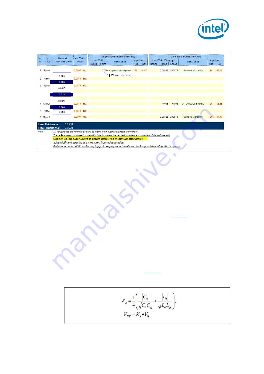
Table 3. Stackup Details
2.2
Backward and Forward Coupling Coefficient Calculation
Some designs require a stackup build that is outside of the ranges provided. In this
case, compare the routing electrical characteristics to the Intel recommendation. It
is important to compare the single-ended and differential impedances. However,
crosstalk level, which is governed by trace spacing, is not implied by the impedance
target. In cases where the selected stackup varies from the Intel recommendation,
we recommend calculating and comparing the backward coupling coefficient to
choose proper trace spacing. The coupling coefficient represents the source voltage
percentage that is coupled to victim lines. As shown in
, Kb is defined as the
backward coupling coefficient. For backward (near-end) crosstalk, inductive and
capacitive coupling are of the same polarity and the noise magnitude is not a
function of trace length. The backward coupling coefficient (Kb) values can be used
to determine trace spacing. For forward (far-end) crosstalk, Kf inductive and
capacitive coupling are of opposite polarity, and the crosstalk magnitude (Vfe) is
proportional to both trace length and edge rate.
Kf is typically a very small value in most practical designs. Therefore, we have not
included the Kf values in the design guide. However, if the value is desired, the
equation for calculating Kf is provided in
Figure 5. Backward Coupling Coefficient


