Intel
®
Pentium
®
III Processor in the FC-PGA2 Package Thermal Design Guidelines
R
249660-001
29
7. With the thermocouple in place, the epoxy can now be mixed and applied. Follow the
manufacturer's directions for mixing the epoxy.
8. Use a clean, finely pointed applicator to apply the epoxy to the bead. Dab the epoxy bond on the
bead and the exposed wires. Use only the appropriate amount of glue to cement the thermocouple
down. The entire bead should be submerged and it is best to have insulated wires protruding from
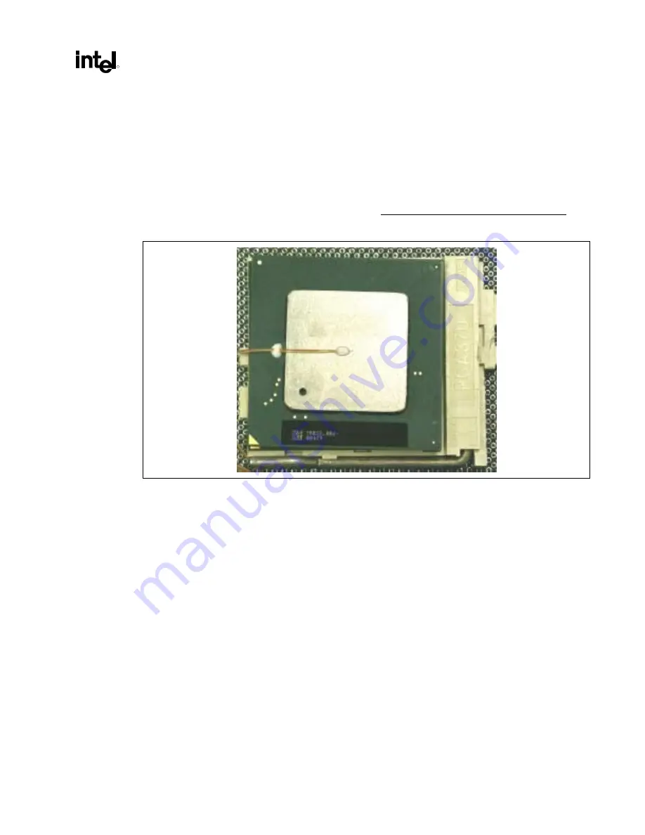
the glue (see Figure 7-6).
9. Additional beads of epoxy can be added, off of the IHS surface, along the length of wire to provide
additional attachment for the thermocouple wire. Only one bead should be on the IHS surface.
Figure 7-6. Thermocouple Adhesive Placement
10. To cure the epoxy, put the part(s) in an oven set @ 150
°
F (65
°
C) for a period of 1 hour. Make sure
the vibration in the oven is minimal to prevent the thermocouple bead from moving. Another
alternative is to cure the epoxy at room temperature for at least 12 hours. (Some epoxy may have
different cure times. Refer to the manufacturer’s instructions.)
11. Once the epoxy has cured, remove all tape and check for any residual epoxy outside the
thermocouple attach area on the IHS. Run the tip of your finger around the IHS surface to find any
small glue dots. Remove any residual glue to prevent any impact on bond line or heatsink attach.
12. Verify the cured adhesive bead at the IHS center is smaller than 0.15 inches (3.8mm) in diameter
and 0.025 inches (0.63mm) in height so as to fit in the hole drilled in the heatsink base. Trim as
necessary.
13. Check the electrical continuity between the thermocouple and the IHS again. If there is no
electrical continuity between the thermocouple and the IHS, repeat steps 4 through 12.
14. Place the TIM on the heatsink base. If it is a semi-liquid type apply it on the IHS around the
thermocouple. The clamping force will spread the TIM. If the TIM is a solid type, punch a 0.15
inch (3.8mm) diameter hole in the center of the TIM pad and cut a line from a side to the hole.
This will allow the installation of the TIM to the IHS with the thermocouple already attached to the
IHS.


