background image

24

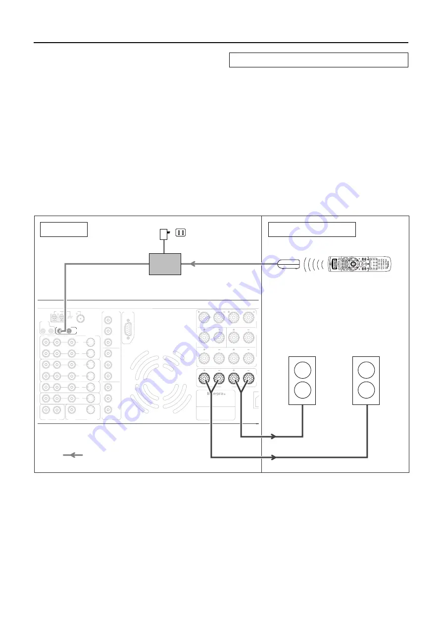
Connecting to the remote zone (Zone 2) input

When using the ZONE 2 SPEAKERS terminals

1. Connect the speaker cables from the speakres

in the remote zone (Zone 2) speaker terminals
on the DTR-7.1.

2. Install the connecting block in the main zone

and connect it to the IR IN ZONE 2 input at the
DTR-7.1.

3. Install the remote sensor in the remote zone

and connect it to the connecting block in the
main zone.

Outline

The IR IN ZONE 2 input allows you to control the DTR-7.1 from
the remote zone (Zone 2) with the remote controller even though
the remote zone is physically separated. The diagram below shows
how to make the proper connections for the remote zone.

The following equipment (sold separately) is essential for
operation from the remote zone:

• Onkyo’s Multi-Room System kits (IR Remote Controller

Extension System), or

• Multiroom A/V distribution and control systems from Niles

®

and Xantech

®

 to name a few

Make connection as shown below. Do not plug the equipment into
the power source until the connection is complete.

R

R

R

L

L

L

P

B

P

R

Y

P

B

P

R

Y

P

B

P

R

Y

COMPONENT

VIDEO

ANTENNA

VIDEO

1

V IDEO

2

DVD

MON ITOR

OUT

V IDEO

3

R

L

INPUT 1

INPUT 2

OUTPUT

VIDEO

S VIDEO

VIDEO

S VIDEO

OUT

OUT

I N

I N

I N

I N

FR
SP

SU
SP

SURR
BACK

SPEAKER

ZO
SP

CE
SP

ER

MAIN

ZONE 2

AM

FM

75

12 V

TRIGGER

A

B

RS


232

MODEL NO. 

DTR-7.1

AV RECEIVER

ZONE 2

MAIN

IR IN

ZONE 2

OUT

R

L

HOME THEATER CONTROLLER

RC-390M

Zone 2

left

speaker

Zone 2

right

speaker

Remote sensor

Remote controller

 Connecting block

DTR-7.1

Connection example for Onkyo’s Multi-room System kit

Mini plug cable

Power supply

Signal flow

Wall outlet

Remote zone (Zone 2)

Main zone

Содержание DTR-7.1

Страница 1: ...ollowing the instructions in this manual will enable you to obtain optimum performance and listening enjoyment from your new AV Receiver Please retain this manual for future reference 2 8 28 56 Before using Facilities and connections Remote controller 48 Enjoying music or videos 68 Appendix Setting OSD menu AV Receiver DTR 7 1 Instruction Manual ...

Страница 2: ... built up static charges Article 810 of the National Electrical Code ANSI NFPA 70 provides in formation with regard to proper grounding of the mast and supporting structure grounding of the lead in wire to an an tenna discharge unit size of grounding conductors location of antenna discharge unit connection to grounding electrodes and requirements for the grounding electrode See Figure 1 15 Lightni...

Страница 3: ...rs heat registers stoves or other appli ances including amplifiers that produce heat FIGURE 1 EXAMPLE OF ANTENNA GROUNDING AS PER NATIONAL ELECTRICAL CODE ANSI NFPA 70 For U S models Note to CATV system installer This reminder is provided to call the CATV system installer s at tention to Article 820 40 of the NEC ANSI NFPA 70 which pro vides guidelines for proper grounding and in particular specif...

Страница 4: ...anel 9 Front panel display 10 Remote controller 11 Rear panel facilities 12 Example of how to connect your equipment 16 Standard connections 17 Connecting your audio components 18 Connecting your video components 18 Connecting speakers 20 Ideal speaker configuration 20 Minimum speaker configuration for surround sound playback 20 Speaker placement 20 Connecting speakers 21 Connecting the speaker ca...

Страница 5: ...mands programmed under a MODE button 63 Using a Macro function 64 What is a Macro function 64 Programming a Macro function 64 Running a Macro function 64 Programming the Direct Macro function 65 Running a Direct Macro function 65 Erasing a macro from the MODE MACRO button 66 Erasing a direct macro from the DIRECT MACRO button 66 Erasing all commands and macros that have been programmed 67 Macro mo...

Страница 6: ...stems Inc 1996 Digital Theater Systems Inc All rights reserved Xantech is a registered trademark of Xantech Corporation Niles is a registered trademark of Niles Audio Corporation THX Select Before any home theatre component can be THX Select certified it must pass a rigorous series of quality and performance tests Only then can a product feature the THX Select logo which is your guarantee that the...

Страница 7: ...nding on usage Using the remote controller Point the remote controller toward the remote control sensor The STANDBY indicator lights up when the unit receives a signal from the remote controller Notes Place the unit away from strong light such as direct sunlight or inverted fluorescent light which can prevent proper operation of the remote controller Using another remote controller of the same typ...

Страница 8: ...Audio R VCR 2 Video 4 Audio Selector 1 2 3 7 4 5 6 8 0 9 PCM DIGITAL DIRECT MEMORY FM STEREO AUTO DOLBY PRO LOGIC SLEEP DTS DSP STEREO TUNED ft ch dB DOLBY DIGITAL 1 2 4 5 6 8 7 3 Front panel facilities See illustration below Here is an explanation of the controls and displays on the front panel of the DTR 7 1 Front panel Front panel display Smart Scan Controller Push To Enter DSP Preset Dimmer Do...

Страница 9: ...e direction of the button you pressed and stop when it tunes into one Front panel Power switch After plugging in the power cord into the rear panel and wall outlet pressing this button connects the DTR 7 1 to the AC mains and turns it on Before turning on the power make sure all cables are properly connected Turning on the DTR 7 1 may cause a momentary power surge that might interfere with other e...

Страница 10: ...er than FM or AM is selected Listening Mode buttons Press these buttons to select a listening mode for the current input source DIRECT Select for direct audio output that does not pass through sound alteration circuits and other filters STEREO Select for normal stereo output j DTS SURROUND Select for the Dolby Pro Logic Dolby Digital or DTS listening modes THX Select for the THX listening mode Rem...

Страница 11: ...n For displaying the OSD Menu However when in the DVD mode this button displays the DVD menu ENTER cursor button When selecting items in the OSD Menu press the upper and lower portions to move the on screen cursor or highlighted portion upward and downward press the right and left portions to select parameter values or modes and press ENTER to display the screen for the selected item VOL button Fo...

Страница 12: ...ities Insert all plugs and connectors securely Improper connections can result in noise poor performance or damage to the equipment Improper connection Inserted completely Here is an explanation of the terminals found on the rear of the DTR 7 1 and how they are used Before connecting your audio and video components be sure to read this section carefully and then proceed to the explanations on how ...

Страница 13: ...t has two z connectors you can use either one to connect to the DTR 7 1 The other one can be used to daisy chain with another component For Integra DVD or MD players you can control them by simply pointing the RC 418M controller directly at the component REMOTE CONTROL Ex CD player Ex cassette tape deck DTR 7 1 z connector z connector PRE OUT These jacks are for connecting auxiliary power amplifie...

Страница 14: ...h turntables that use moving magnet cartridges RCA type AC OUTLETS AC 120V 60Hz SWITCHED TOTAL 120W 1A MAX MONITOR OUT The monitor output includes both composite video and S video configurations This output is for connecting television monitors or projectors SPEAKERS 6 terminals are provided for the front left front right front center surround left surround right and surround back speakers Speaker...

Страница 15: ...use with the DTR 7 1 and should not be used with any other adevice Never have the power cord disconnected from the DTR 7 1 while the other end is plugged into the wall outlet Doing so may cause an electric shock Always connect by plugging into the wall outlet last and disconnect by unplugging from the wall outlet first Composite video jack S video jack VIDEO IN OUT These are the video inputs and o...

Страница 16: ...D PH R L VIDEO S VIDEO OUT OUT IN IN IN IN CENTER SB CENTER R L ZONE 2 MAIN IR IN AM IN FM 75 ZONE 2 OUT 12 V TRIGGER A B R L Satellite tuner or TV VIDEO 3 6 Refer to page 19 Example of how to connect your equipment VCR VIDEO 2 5 Refer to page 18 Tape deck MD recorder DAT deck CD recorder TAPE 3 Refer to page 18 CD player CD 2 Refer to page 18 Turntable PHONO 1 Refer to page 18 DVD player DVD 4 Re...

Страница 17: ...heir features to ascertain which method of connection is best Be sure to always refer to the instruction manual that came with the component that you are connecting Do not plug in the power cord until all connections have been made For input jacks red connectors marked R are used for the right channel white connectors marked L are used for the left channel and yellow connectors marked V are used f...

Страница 18: ... of the DTR 7 1 is only the digital signal input to the DIGITAL INPUT jack Connecting your video components Below is an example of how you can connect your video components to the DTR 7 1 Refer to the diagram on pages 16 and 17 for the following connection examples The flow of the video signals is as follows The signal that comes in from VIDEO IN is sent to VIDEO OUT The signal that comes in from ...

Страница 19: ...DEO 1 IN jacks on the DTR 7 1 and video input terminal to the VIDEO 1 OUT jacks If there is an S video input output terminal on the device connect it to the S VIDEO 1 IN OUT jack using an S video cable If the device has component video outputs connect them to one of the COMPONENT VIDEO INPUT jacks Using an RCA type audio connection cable connect the audio output terminal on the device to the same ...

Страница 20: ...nt and produces environmental sound associated with the background and effect sound for each scene Surround back speaker Required for enjoying THX Surround EX audio For audio using surround back right and surround back left speakers a separately sold 2 channel power amplifier is required Subwoofer Produces powerful and heavy bass Minimum speaker configuration for surround sound playback Front righ...

Страница 21: ...RE OUT SUBWOOFER jack and the subwoofer to the amplifier Surround back speaker Front left speaker Front right speaker Surround left speaker Surround right speaker Center speaker Subwoofer 1 3 4 5 2 5 8 Connecting speakers Notes The DTR 7 1 is designed to produce optimum sound quality when speakers with impedances within the specified ranges are connected Check the following information and choose ...

Страница 22: ... attached FM indoor antenna the use of an outdoor antenna is recommended Connecting the AM loop antenna The AM loop antenna is for indoor use only Set it in the direction and position where you receive the clearest sound Put it as far away as possible from the DTR 7 1 televisions speaker cables and power cords When reception is not satisfactory with the attached AM loop antenna alone connection of...

Страница 23: ...and electrical shock grounding is necessary Follow item 14 of the Important Safeguards on page 2 when you install the outdoor antenna Directional linkage Do not use the same antenna for both FM and TV or VCR reception since the FM and TV or VCR signals can interfere with each other If you must use a common FM TV or VCR antenna use a directional linkage type splitter Connecting an FM outdoor antenn...

Страница 24: ...ntial for operation from the remote zone Onkyo s Multi Room System kits IR Remote Controller Extension System or Multiroom A V distribution and control systems from Niles and Xantech to name a few Make connection as shown below Do not plug the equipment into the power source until the connection is complete R R R L L L PB PR Y PB PR Y PB PR Y COMPONENT VIDEO ANTENNA VIDEO 1 VIDEO 2 DVD MONITOR OUT...

Страница 25: ... 2 SB CENTER R L AC OUTLETS AC 120V 60Hz SWITCHED TOTAL 120W 1A MAX AM IN FM 75 12 V TRIGGER A B RS 232 AC INLET MODEL NO DTR 7 1 AV RECEIVER CAUTION SPEAKER IMPEDANCE 6 OHMS MIN PER EACH SPEAKER TERMINAL ZONE 2 MAIN IR IN ZONE 2 OUT R L ZONE 2 OUT R L ZONE 2 MAIN IR IN HOME THEATER CONTROLLER RC 418M Main zone Remote sensor Remote controller Zone 2 speaker Zone 2 speaker Zone 2 amplifier Signal f...

Страница 26: ... speakers connect a power amplifier to the PRE OUT SURR BACK terminals on the DTR 7 1 and connect the surround back speakers to that power amplifier You will also need to make the appropriate setting in the OSD Menu Speaker Setup Speaker Config Surr Back Out see page 30 PRE OUT R L R L SB FRONT SURR SURR BACK SUB WOOFER CENTER 1 5 6 7 8 2 3 4 R R R L L L FRONT SPEAKERS SURR SPEAKERS SURR BACK SPEA...

Страница 27: ...the first time the DTR 7 1 will automatically enter the standby state and the Standby indicator will light same condition after step 2 below Before you plug in the DTR 7 1 confirm that all connections have been made properly Turning on the power may cause a momentary power surge which might interfere with other electrical equipment on the same circuit such as computers If this happens use a wall o...

Страница 28: ...ker Config 2 Speaker Distance 3 Level Calibration 4 Bass Peak Level ENTER Quit OSD Menu 1 Speaker Setup 2 Input Setup 3 Listening Mode Setup 4 Preference 5 OSD Setup ENTER Quit OSD The On Screen Display OSD menu The OSD menu is a settings menu that is displayed on your TV monitor and allows you to perform your speaker settings setup your input sources set the listening modes and much more In most ...

Страница 29: ...f the monitor is connected to MONITOR OUT VIDEO of the DTR 7 1 then preform the operations given below and set the OSD output to Video The initial setting is S Video 1 Press the Menu button 1 Speaker Setup appears in the front display 2 Turn the SSC dial to the right to display 5 OSD Setup and press the SSC dial OSD Config appears 3 Press the SSC dial OSD Out S Video appears 4 Turn the SSC dial to...

Страница 30: ...eakers are connected Large Select if the surround left and right speakers are large sized Small Select if the surround left and right speakers are small sized If Small is selected for the Front setting then Large cannot be selected for this setting e Surr Back None Select if no surround back left and right speakers are connected Large Select if the surround back left and right speakers are large s...

Страница 31: ...tervals e Surr Back R Set the distance from the surround back right speaker to your normal listening position between 1 and 30 feet in 0 5 feet intervals 0 3 to 9 meters in 0 15 meter intervals This setting appears if set for two surround back speakers in the Speaker Config sub menu f Surr Back L Set the distance from the surround back left speaker to your normal listening position between 1 and 3...

Страница 32: ...lume automatically increases to the reference level 0dB Remember the level of this noise and then press the cursor button Note that this can be adjusted to any level between 12 and 12 decibels in 1 decibel intervals The DTR 7 1 will now emit the pink noise from the center speaker 2 Using the and cursor buttons adjust the volume level of the noise from the center speaker so that it is the same leve...

Страница 33: ... dial to slowly raise the volume to the point where the sound becomes distorted and then back it off until it returns to normal This is the proper setting for the bass peak level After setting the Peak Level at the Bass Peak Level sub menu press the EXIT button The values are set and the previous screen appears Menu 1 Speaker Setup 2 Input Setup 3 Listening Mode Setup 4 Preference 5 OSD Setup ENTE...

Страница 34: ... TAPE VIDEO 4 VIDEO 3 OPTICAL 2 VIDEO2 VCR2 VIDEO1 VCR1 COAXIAL 2 DVD COAXIAL 1 Available for digital input but not set in initial settings Not available for digital input 2 Input Setup menu This menu allows you to setup the various input sources available with the DTR 7 1 Each input source may have a great number of settings that are difficult to keep track of so we recommend making a chart to re...

Страница 35: ...and use the digital input jacks OPTICAL or COAXIAL to connect the DTS source If you play a CD or LD that supports DTS when All is selected you may hear a noise for a short while until the DTS decoder recognizes the DTS encoded signal and starts operating This is not a malfunction If you press the PAUSE or SKIP button on the player while playing a DTS source a short noise may be heard This is not a...

Страница 36: ...o Setup sub menu Input source selected Video CD Last PHONO Last FM Last AM Last TAPE Last DVD DVD VIDEO1 VIDEO1 VIDEO2 VIDEO2 VIDEO3 VIDEO3 VIDEO4 VIDEO4 Last When you change to an input source set to Last the video of the input source that you changed from is continued For example if the selected input source is VIDEO 1 and you then change to CD set to Last then the audio from the CD input is pla...

Страница 37: ...r example if your DVD player also plays compact discs and the DVD video signal is DTS and the compact disc signal is PCM then you can set a different listening mode for each This is especially convenient if you frequently play the same types of movies or music Input source signals a 2ch Source Set a listening mode for the input signal from 2 channel analog sources PCM sources and 2 0 channel Dolby...

Страница 38: ...re of a movie theater THX This mode is for playing back sources using THX This mode will work well with 5 1 channel Dolby Digital and DTS sources and Dolby encoded sources For excellent fidelity when playing back THX sounds it is recommended to use a THX certified speaker system THX Cinema This is the conventional 5 1 channel THX format This mode should be used only when playing back sources that ...

Страница 39: ...ers The sound effects moving smoothly toward the surround back This mode is good for music and TV sports programs Orchestra This mode is appropriate for classical and opera music The center channel is cut and the surround channels are emphasized to widen the stereo image It will simulate the natural reverberation that is created in large halls TV Logic This mode gives realistic acoustics to TV pro...

Страница 40: ...the input source is selected Off Select when no device is connected to the 12V TRIGGER B terminal or you do not want the connected device to activate Menu 1 Speaker Setup 2 Input Setup 3 Listening Mode Setup 4 Preference 5 OSD Setup ENTER Quit OSD 2 Input Setup Input DVD a Audio Setup b Video Setup c Listening Mode Preset d Tone Control e IntelliVolume f 12V Trigger ENTER Quit OSD 2 5 IntelliVolum...

Страница 41: ...reo Setup 2 Theater Dimensional Setup 3 Surround Setup 4 THX Setup 5 Mono Movie Setup ENTER Quit OSD 3 1 Stereo Setup a Subwoofer On Quit OSD 3 2 Theater Dimensional Setup Select this to modify the Theater Dimensional T D listening modes The parameters that can be set are shown in the table below Parameter Setting Initial value a Subwoofer Off On On b Listening Angle 20deg 40deg 40deg c Center Off...

Страница 42: ...ge Large Surround Back can only be selected when two surround back speakers are connected to the DTR 7 1 3 11 All Ch Stereo Setup Select this to modify the All Ch Stereo listening mode The parameters that can be set are shown in the table below Parameter Setting Initial value a Subwoofer Off On On b Re EQ Off On Off 3 7 8 9 and 10 Orchestra Setup Unplugged Setup Studio Mix Setup TV Logic Setup Sel...

Страница 43: ...tputs using DTS ES playback regardless of whether or not the signal contains ES identifiers Off Does not output using DTS ES playback regardless of whether or not the signal contains ES identifiers DTS is used However if the surround channel is monaural or nonexistent the playback is made using normal DTS regardless of the above setting For DTS ES playback DTS ES is displayed for the listening mod...

Страница 44: ...log sound level from the center speaker if it is difficult to hear On Enhances the vocal ranges for the center channel signal Off Outputs the center channel signal at the regular level and frequency characteristics Front left speaker Front right speaker Listening angle Listening mode Direct Stereo T D Surround THX Mono Movie Enhanced 7 All Ch Theater Orchestra Stereo Dimensional Unplugged Studio M...

Страница 45: ...lume as a decibel value on a scale with a designated reference point that is displayed as 0 which equals the volume setting of 62 for the absolute display method With this display method the minimum value is the next highest is 61 and the maximum value is 18 b Maximum Volume This setting allows you to set the maximum volume that can be output with the Master Volume Dial To Prevent Components From ...

Страница 46: ...p ENTER Quit OSD 5 OSD Setup 1 OSD Config 2 OSD Setup 3 OSD Position ENTER Quit OSD 5 1 OSD Config a OSD Output S Video Quit OSD 5 1 OSD Config sub menu a OSD output This setting allows you to set the output of the ODS Menu Select the video terminal to which your monitor is connected S VIDEO or VIDEO S Video Outputs the OSD Menu through the S VIDEO MONITOR OUT terminals Video Outputs the OSD Menu ...

Страница 47: ...sition of the OSD menu as it is displayed on your screen Depending on the monitor used there may be cases where the OSD menu is not displayed in the center and parts of the menus are cut off To adjust the position of the OSD menu simply press the cursor buttons to inch the menu to position you desire OSD Setup a Background Color Select either Blue1 Blue2 Green1 Green2 Magenta Red1 or Red2 as the b...

Страница 48: ...ne 2 terminal is an analog output Digital signals are not output If no sound is heard from the selected input source To select the same source for the remote zone that is selected for the main zone press the Zone 2 button again until Zone2Sel SOURCE appears in the display Controlling the DTR 7 1 without the remote controller 1 Press the Zone 2 button on the DTR 7 1 2 Select a source After pressing...

Страница 49: ...aural mode To return to stereo press the FM Mute Mode button again AUTO appears Some inter station noise may be heard but the sound will not cut in and out as it would if stereo was selected The tuner frequency changes in 50 kHz increments for FM and 10 kHz increments for AM When tuning into FM stations you can press the Tuning Up or Down button continuously for more than 0 5 seconds to scan for a...

Страница 50: ... Light This programs the radio station as a preset radio station Up to 40 stations can be stored in memory as preset radio stations You can enter text names for any of the preset radio stations see page 55 Presetting a radio station 1 Tune into the radio station you desire see Tuning into a radio station 2 Press the Character Memory button on the front panel 3 Turning the SSC dial select a preset ...

Страница 51: ...ress the button on the front panel or on the remote controller that corresponds to the input source you want After you have selected the input source simply turn on the corresponding component and play the media Adjusting the volume Adjusting the main volume adjust the volume level output from all the speakers connected to the DTR 7 1 together If headphones are connected this also adjusts the volu...

Страница 52: ...ach input source so that when the source is selected the name of that source is displayed in the front display of the DTR 7 1 see page 55 Temporarily changing the speaker output levels To change the individual speaker volumes temporarily use the remote controller and follow the procedure given below Note that the calibration settings will return to the original settings when the DTR 7 1 is put in ...

Страница 53: ...y selected input source You cannot record the surround effects Digital signals input to the DIGITAL INPUT COAXIAL and DIGITAL INPUT OPTICAL inputs will be output to the DIGITAL OUTPUT OPTICAL output Digital input signals are only output to the digital outputs and analog input signals are only output from the analog outputs There is no conversion from digital to analog or vice versa When connecting...

Страница 54: ...eo camera connected to the VIDEO 4 IN 4 Insert a video tape for recording in the video cassette recorder connected to VIDEO 1 OUT 5 Press the Rec Out button repeatedly until Rec Sel SOURCE appears in the front display Now CD has been selected as the audio input source and VIDEO 4 as the video input source 6 Start recording on the video cassette recorder and start playing at the CD player and video...

Страница 55: ...the Character Memory button Name In appears 3 Press the SSC dial Now you can change the name 4 Press the Tuning Up Down button to select the character you wish to change 5 Rotate the SSC dial to select the character you wish to enter and then press the SSC dial The name entry mode is canceled automatically when you finish entering 10 characters If you enter a name of less than 10 characters press ...

Страница 56: ... to turn on the DTR 7 1 and press the STNBY button to put it back in the standby mode When you press the STNBY button on the remote controller it puts the DTR 7 1 in the standby state but does not turn it completely off SEND LEARN indicator This indicator acts as a guide when commands are programmed into or sent by the remote controller It also warns the user when an error is made or battery power...

Страница 57: ...urround listening mode If Dolby Digital or DTS was already set as the listening mode The operating mode for the 6 1 channel matrix playback of sources that allow 6 1 channel matrix playback will change as follows see page 43 Auto On Off Auto DIRECT Changes the listening mode directly to the Direct listening mode If pressed the listening mode for the selected input source set in the Listening Mode ...

Страница 58: ... 1 Press the MD MODE button MD appears in the remote controller display 2 Press the desired operation button The buttons shaded in the figure to the left are the operation buttons that can used to control an Onkyo mini disc player ON STNBY Turns the mini disc player on and off Track down Track up Play Stop Fast reverse Fast forward REC o Record Pause r Eject the disc 1 to 9 10 Numeric keys ENT Ent...

Страница 59: ...he DTR 7 1 Calling up a preset radio station 1 Press the AUDIO TAPE MODE button AUDIO appears in the remote controller display 2 Press the TUN input selector button TUN appears in the remote controller display and momentarily and then AUDIO reappears 3 Press the CH or button to select the desired the preset station number HOME THEATER CONTROLLER RC 418M OPEN COLSE REC AUDIO MUTING DISC TRACK DVD C...

Страница 60: ...G Activates the muting function at the DTR 7 1 Note The ENT button on the bottom right of the numeric keys has the same function as ENTER of the ENTER cursor button SAT CABLE VCR and TV MODE buttons No preset codes are programmed into the SAT CABLE VCR and TV MODE buttons You can use these buttons to program the remote controller signals of other devices see page 61 You may use the following butto...

Страница 61: ...M remote controller will change to the commands you program here to operate the compact disc player After programming which MODE button to use you will then transfer the separate commands from the other remote controller over to the RC 418M remote controller one at a time Each command is then programmed to a different button on the RC 418M remote controller Any button is programmable for this step...

Страница 62: ...in the display and the remote controller exits the programming mode Resume from Step 2 If a failure occurs during programming the SEND LEARN indicator flashes three times quickly NG appears in the display and the remote controller exits the programming mode Resume from Step 3 If a failure occurs five times in row during programming ERROR appears in the display and the remote controller exits the p...

Страница 63: ... again The SEND LEARN lamp flashes twice slowly and CLEAR appears in the display The memorized command is erased Note If no button is pressed for more than 30 seconds during the programming the SEND LEARN indicator flashes three times quickly ERROR appears in the display and the remote controller exits the programming mode Resume from Step 1 Erasing all the commands programmed under a MODE button ...

Страница 64: ...the remote controller exits the programming mode Resume from Step 1 Running a Macro function Perform the procedure below to run a macro function that you have programmed into the remote controller After programming a macro you should always run it at least once to make sure that it has been programmed properly 1 Point the remote controller at the DTR 7 1 and press the CD MODE button 2 Press the MO...

Страница 65: ... indicator flashes three times quickly ERROR appears in the display and the remote controller exits the programming mode Resume from Step 1 If you perform an invalid operation during programming the SEND LEARN indicator flashes three times quickly ERROR appears in the display and the remote controller exits the programming mode Resume from Step 1 Running a Direct Macro function Perform the procedu...

Страница 66: ... button and then release both buttons When you press the MODE button the SEND LEARN indicator lights and that mode appears in the display When you press the DIRECT MACRO button the indicator turns off When you release the buttons the indicator flashes once and M 01 appears in the display 2 Press the DIRECT MACRO button again The SEND LEARN indicator flashes twice slowly and CLEAR appears in the di...

Страница 67: ...n the display All programmed commands and macros are erased and the remote controller returns to its factory presets Notes Proceed to Step 3 immediately after Step 2 otherwise the batteries will be consumed quickly If you press any button other than the ENT button in Step 3 nothing will be erased In this case resume from Step 1 MACRO MODE MODE MODE MODE MODE MODE MODE MODE DIRECT MACRO MACRO MACRO...

Страница 68: ...ppropriate volume page 32 CENTER SPEAKER is set to None Set CENTER SPEAKER to Large or Small page 30 No sound or very low volume from subwoofer Subwoofer is set to No Check the speaker setting page 30 Subwoofer speakers output level setting is improper Check the output level of the Subwoofer using the test tone Low frequency humming is heard Not properly grounded Check outer conductor of input plu...

Страница 69: ...the position or direction of the outdoor antenna No preset station is recalled Power cord has been unplugged or the POWER switch has been turned off for a long time The memory contents are lost Store all stations again VIDEO and AUDIO Desired picture does not appear Improper connection Check the connection again Insert the plugs and connectors completely Video Setup sub menu of Input Setup menu se...

Страница 70: ...t display and the DTR 7 1 enters the standby state REMOTE CONTROLLER Front panel controls function but remote controller controls do not No batteries in remote controller Insert batteries Batteries have worn out Replace batteries Remote controller is not pointed at the remote sensor of the DTR 7 1 Point the remote controller at the remote sensor of the DTR 7 1 Remote controller is too far from the...

Страница 71: ...z 0 5 T H D Frequency Response 20 Hz to 30 kHz 1 dB CD in Direct mode 5 Hz to 100 kHz 1 dB 3 dB CD in Direct mode RIAA Deviation 20 to 20 kHz 0 8 dB Tone Control Bass 10 dB at 100 Hz Treble 10 dB at 10 kHz Signal to Noise Ratio Stereo Phono 80 dB IHF A 5 mV input CD Tape 100 dB IHF A 0 5 V input Muting 50 dB TUNER SECTION FM Tuning Range 87 5 to 108 0 MHz 50 kHz steps Usable Sensitivity Mono 11 2 ...

Страница 72: ...Williams Drive Ramsey N J 07446 U S A Tel 201 825 7950 Fax 201 825 8150 E mail integra onkyousa com Integra Division of ONKYO CORPORATION Sales Product Planning Div 2 1 Nisshin cho Neyagawa shi OSAKA 572 8540 JAPAN Tel 072 831 8111 Fax 072 833 5222 SN 29342973 ...

Отзывы: