


5
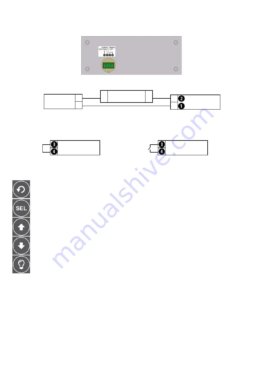
LPI-LCD-6 Terminal Layout.
Included with your LPI-LCD-6 is a wiring sticker, which should be applied to the back panels, after the unit has been
mounted. The LPI-LCD-6 is powered from the 4~20mA loop input signal and connects to terminal 1 & 2.
LPI-LCD-6 Wiring Diagrams.
+
-
4~20mA Output
Device.
+
Power Supply
24Vdc.
-
-
+
LPI-LCD-6
Loop Indicator.
The LPI-LCD-6 also features a display lock to prevent tampering after the unit has been configured (except for the
Backlight button
L
). In order to lock out the LPI-LCD-6 display buttons, terminals 3 & 4 need to be shorted out.
This means you could also connect a switch between terminals 3 & 4 to enable toggling of this feature.
LPI-LCD-6
Loop Indicator.
LPI-LCD-6
Loop Indicator.
LPI-LCD-6 Buttons & Display.
BACK
:
Steps backward in the setup menu, without saving changes.
Display Screen.
The screen can display 1~6 characters to reflect the condition of your 4~20 input in normal operating mode.
The character on the right may be set up to display units (any letter from A~Z - see page 6 to configure), the default
setting is for the screen to display up to a 6 digit number with no units. KG/LB/T are pre-set special units for common
weight units, and appear to the right of the 6th character. (see page 6 also to select).
BACKLIGHT
:
Activates the screen backlight for period of 1~9 seconds (default = 3 seconds, see page 7 to
alter). Note that the backlight charges off the input signal, and may appear dimmer if used
repeatedly or immediately after the instrument has been connected.
DOWN
:
Scrolls downwards through options or decreases values in the setup menu.
UP
:
Scrolls upwards through options or increases values in the setup menu.
MENU
:
Accesses the main menu from the operational display. Also used to select your settings in
the setup menu.


