


Specifications subject to change without notice. | USA 140924 | Page 3 of 6
INTEC Controls | 12700 Stowe Drive, Suite 100, Poway, CA 92064 | Ph: (858) 578.7887 & (888) GO.INTEC | inteccontrols.com
LGC-CO
SPECIFICATIONS
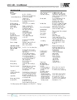
Physical,
Controller
Enclosure (panel)
- material
Polycarbonate, impact
resistance EN 50102/IK08,
flammability rating UL 94-5V
- conformity
UL Type 1, UL 508/UL 50 standards
- color
Light gray, smoked gray for cover
- protection
NEMA 4X (IP65)
- installation
Wall (surface) mounted
Dimensions (H x W x D)
- base
7.9 x 7.5 x 4.1 in.
(200 x 190 x 105 mm)
Cable entry
5 holes for 1/2 in. conduit,
covered
Wire connection
Terminal blocks,
Push-on connect and screw type
for lead wire
Wire size
- input
Min. 22 AWG (0.34 mm
2
)
Max. 16 AWG (1.50 mm
2
)
- output
Min. 24 AWG (0.25 mm
2
)
Max. 14 AWG (2.50 mm
2
)
Weight
4.5 lbs (2.0 kg)
Enclosure (panel) approval UL Listed, E75645
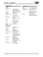
Physical,
Sensor/Transmitter
Enclosure, standard
- material
Polycarbonate,
UL 94-HB, fire-retardant
- conformity
UL 50
- color
Light gray
- protection
NEMA 4X (IP65)
- installation
Wall (surface) mounted, or
single gang electrical box
Dimensions (H x W x D)
5.12 x 3.31 x 2.95 in.
(130 x 84 x 75 mm)
Cable entry
1 hole for 1/2 in. conduit for wall
(surface) mounting and
1 hole on back side of base plate
for single gang electrical box
mounting
Wire connection
Terminal blocks,
screw type for lead wire
Wire size
Min. 24 AWG (0.25 mm²),
Max. 14 AWG (2.5 mm²)
Wire distance
Max. loop resistance 500 Ω
(= wire resistance plus controller
input resistance)
Weight
0.6 lbs (0.25 kg)
Enclosure approval
UL Listed, E208470
CSA Certified, E208470
Approvals / Listings
System
NRTL Perf. Tested & Certified:
- sensor/transmitter
Conforms to ANSI/STD UL 2075
- controller
Conforms to ANSI/STD UL 2017
- transmitter & controller
City of Los Angeles
CE
VDI 2053, air treatment systems
for garages and tunnels
EMC-Compliance 89/336/EWG,
LVD 73/23/EWG
Warranty
Two years material and
workmanship, 12 months normal
exposure for sensor element
INTEC Controls | 12700 Stowe Drive, Suite 100, Poway, CA 92064 | Ph: (858) 578.7887 & (888) GO.INTEC | inteccontrols.com
Specifications subject to change without notice. | USA 200211 | Page 29 of 30
LGC-LG2 – UserManual


