


Customer Services (858) 578-7887 & (888) GO IN
TEC
IN
TEC
Controls, 12700 Stowe Dr., Suite 1
0
0, Poway, CA 92064
Fax (858) 578-4633 & (888) FX IN
TEC
www.inteccontrols.com
Specification subject to change without notice.
Printed in USA 131119
Polygard® is a registered trademark of MSR
LGC/LG2-04
PolyGard
®
Multi-Point Controller
User Manual - LGC/LG2-04
Page 20
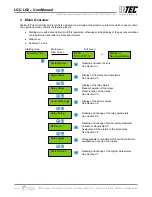
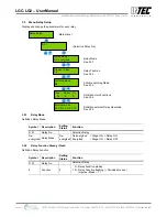
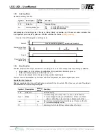
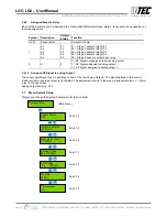
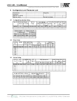
3.7.6 Time, Date
Input and correction of the system time and date. Selection of the time and date format.
Symbol Description Default
Status
Function
US
Time format US
EU = Display time and date in EU format
US = Display time and date in US format
hh.mm.ss Time
hh.mm.ss = Input the correct time (EU format)
hh.mm.ss am = Input the correct time (US format)
TT.MM.JJ Date
TT.MM.JJ = Input the correct date (EU format)
MM.TT.JJ = Input the correct date (US format)
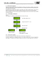
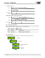
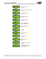
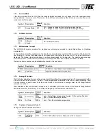
3.7.7 Analog Output
The Controller has two analog outputs (AO) with 4 to 20 mA signal per control module. Each of the analog outputs
can be assigned the signal of one or more sensor points. The assignment occurs in the menu „SP Setup“ for
each SP. The sensor point sends the signal that is defined in the menu „C/A Mode“.
The Controller determines from the signal of all assigned sensor points the minimum, the maximum or the average
value and sends this value to the analog output. The determination of which value is sent is defined in this menu
„Analog Output X“. The analog output can be calibrated with for 4 and 20 mA. In addition the AO can be adjusted
with an ampere meter attached (measuring range 25 mA) then respective AO factor can be changed to adjust the
analog output 4 and/or 20 mA . During AO calibration no evaluation is made of the sensor point signals. This
calibration is factory-set. The factors should only be changed if you have an accurate amp meter.
Symbol Description Default
Status
Function
Max.
Select
Output mode Max.
Min. = Spends the minimum value of all assigned SP
Max. = Spends the maximum value of all assigned SP
Average = Spends the average value of all assigned SP
4.0
20.0
Calibration
4.0
20.0
4.0 = Calibration factor at 4 mA
20.0 = Calibration factor at 20 mA
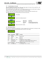
3.7.8 Define the Failure Relay
Define the Failure Relay. See also malfunction management (3.1)
Symbol Description Default
Status
Function
05
Failure Relay R05
R05 = Define the failure relay
3.7.9 Power On Time
Sensors need a warm up period, until the chemical process of the sensor reaches a stable condition. During this
warm up period the current signal can lead to unwanted false alarm. Therefore the Controller starts reporting after
switching on of the power supply and the delay On Time is passed. While this time runs off, the Controller does not
report alarms. The power on status is displayed in the display.
Symbol Description
Default
Status
Function
30 s
Power On Time 30 s
XX = Define the Power On Time (sec.)
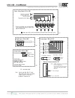
3.7.10 Activation of expansions modules
The Multi point Controller can have expansions modules; therefore only activate Expansions modules for every
four sensor points in addition to the controller module.
Specifications subject to change without notice. | USA 131119 | Page 20 of 30
12700 Stowe Drive, Suite 100, Poway, CA 92064 | Ph: (858) 578.7887 & (888) GO.IN
TEC
| relevantsolutions.com/inteccontrols
LGC-LG2 – UserManual
Polygard® is a registered trademark of MSR | LGC/LG2-04
Specifications subject to change without notice. | USA 160104 | Page 20 of 30
12700 Stowe Drive, Suite 100, Poway, CA 92064 | Ph: (858) 578.7887 & (888) GO.IN
TEC
| relevantsolutions.com/inteccontrols
LGC-LG2 – UserManual
PolyGard
®
is a registered trademark of MSR-Electronic GmbH | LGC/LG2-04
INTEC Controls | 12700 Stowe Drive, Suite 100, Poway, CA 92064 | Ph: (858) 578.7887 & (888) GO.INTEC | inteccontrols.com
Specifications subject to change without notice. | USA 200211 | Page 20 of 30
LGC-LG2 – UserManual


