


INSYS ISDN TA 4.0
Connections
4.4
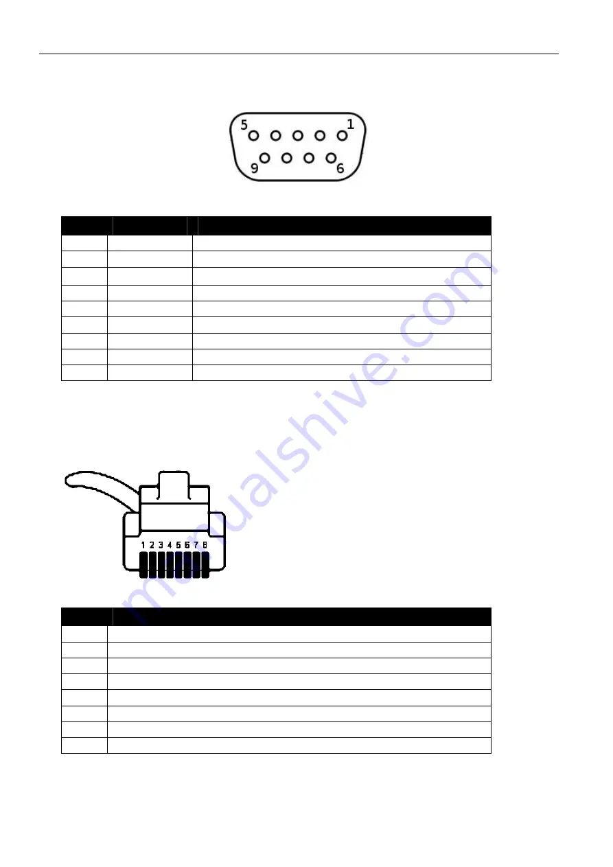
Pin Assignment of the Serial Interface
Figure 5: 9-pin Sub-D socket at the device
Pin
Signal
Description
1 DCD
Data
Carrier
Detect
2 RXD
Receive
Data
3
TXD Transmit
Data
4
DTR
Data Terminal Ready
5 GND
Ground
6
DSR
Data Set Ready
7 RTS
Request
To
Send
8
CTS
Clear To Send
9 RI
Ring
Indication
Table 9: Description of the pin allocation of the Sub-D socket
4.5
Pin Assignment of the S0 Interface
Figure 6: 8-pin Western connector (front view)
Pin
Signal
1 not
connected
2 not
connected
3 a2
4 a1
5 b1
6 b2
7 not
connected
8 not
connected
Table 10: Assignment of the RJ45 connector
23
Содержание ISDN TA 4.0
Страница 1: ...Manual INSYS ISDN TA 4 0...
Страница 2: ......
Страница 6: ...Content 6 Jun 12 19 Tables and Diagrams 96 19 1 List of Tables 96 19 2 List of Diagrams 96 20 Index 97...
Страница 100: ......


