


Instrumentation GDD Inc. 2018-04-06
Page 114
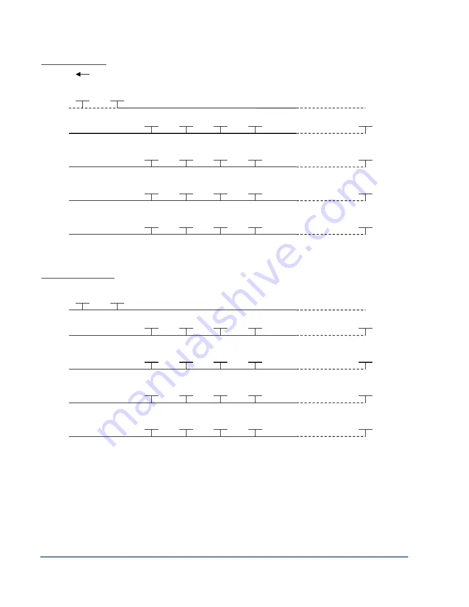
Pole-Dipole (4/8)
Line
Tx
Line
Rx1
Line
Rx2
Line
Rx3
Line
Rx4
Dipole-Dipole (4/8)
Line
Tx
Line
Rx1
Line
Rx2
Line
Rx3
Line
Rx4
C1
C2
PR1
P1
P2
P3
P8
C1
C2
PR1
P1
P2
P3
P16
INFINITY
PR2
P9
P10
P11
P16
PR3
P17
P18
P19
P24
PR4
P25
P26
P27
P32
PR2
P9
P10
P11
P16
PR3
P17
P18
P19
P24
PR4
P25
P26
P27
P32
Содержание GRx8mini
Страница 7: ...Instrumentation GDD Inc 2018 04 06 Page 7 A B C D F G H I J K L M optional N O P Q E...
Страница 63: ...Instrumentation GDD Inc 2018 04 06 Page 63 2 If you want to verify the GPS time select Check GPS...
Страница 83: ...Instrumentation GDD Inc 2018 04 06 Page 83 4 The Allegro2 can now be accessed from the Windows File Explorer...
Страница 101: ...Instrumentation GDD Inc 2018 04 06 Page 101...
Страница 102: ...Instrumentation GDD Inc 2018 04 06 Page 102...
Страница 104: ...Instrumentation GDD Inc 2018 04 06 Page 104...
Страница 131: ...Instrumentation GDD Inc 2018 04 06 Page 131 3D Survey Pole Dipole 2 16...
Страница 138: ...Instrumentation GDD Inc 2018 04 06 Page 138 5 Your next setup on the field should be like this...


