insize ISP-A5000 Скачать руководство пользователя страница 6

5

Set  Factory  Settings:  All  the  engineering  settings  are  set  to 
factory default parameters.

Configure  Footswitch:  Enables  the  user  to  assign  any  key  from 
keyboard to footswitch 1 and 2.

X, Y Liner Setup

Scale  Resolution:  Sets  the  scale  (encoder)  resolution

(

0.1,  0.2, 

0.5, 1, 2, 5, 10, 20, 50µm

).

Display Resolution: Sets the display resolution

(

0.1, 0.2, 0.5, 1, 2, 

5, 10, 20, 50µm

).

Axis


Direction: Sets encoder counting direction.

Machine


ref: Sets machine reference for the axis.

Count per Revoln (CPR): In case of auto, the DRO calculates the 
counts  between  the  two  index  marks  and  calculates  the  CPR 
automatically. In case of manual selection the user needs to enter 
the CPR value.

Resolution  (Deg):  Selects  the  display  resolution  for  the  angular 
axis

(

0.5, 0.2, 0.1, 0.05, 0.01, 0.005, 0.001, 0.0005°

)

.

Axis


Direction: Sets encoder counting direction

(

CW or CCW

)

.

Machine


Ref: Sets machine reference for the axis.

Count Mode: Selects the counting mode

(

Rollover or Continues

)

.

Display Mode: Selects the display units: DDMMSS or DDDEC

.

Axis Lock: Enables / Disables the angular axis position settings.

Z Angular Axis

Axis  calibration  is  required  to  compensate  for  errors  arising  due  to 
wear and tear in machine, encoder misalignment etc. Each axis can 
be calibrated for Linear Errors or Segmented errors as applicable.

Axis Calibration

22

Screen  Gain  (<10000)  –  This  sets  the  gain  of  the  amplifier.  The 
gain  depends  on  the  magnification  and  the  light  source.  Adjust 
this such that the Screen intensity on light region displays counts 
above  3000  counts  to  4000.  In  case  of  higher  magnifications 
where the counts doesn't reach the required value even if the gain 
is set to 100, then minimum of 2000 counts should be ensured for 
good results. Press {             }key to set the gain value.

Now bring the screen sensor in the light region and press {            } 
key.
Now move the screen sensor in to dark region. Press {            } k ey 
to  teach  dark  to  the  DRO.  Here  note  that  the  counts  in  the  dark 
region are less than that in the light region.
NOTE:  Every  time  the  light  intensity  changes  it  is  recommended 
to  te a ch  l i g h t  a n d  d a rk  re g i o n  to  th e  D R O  fo r  p ro p e r 
measurements. No need to change the gain of the system.
Now  perform  Edge  calibration.  In  this  mode  the  selection  is 
provided  for  bore  or  shaft  measurements.  If  the  user  wants  to 
check  bore  jobs  he  has  to  perform  bore  calibration  using  F.O. 
Edge detection prior to measurements.

NOTE:  It  is  mandatory  to  calibrate  the  type  of  job  either  bore  or 
shaft prior to measurements using F.O. Edge detection.

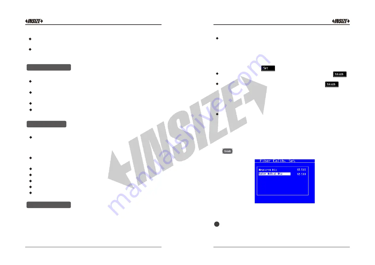
Now  probe  the  circle  as  per  procedure  explained  earlier.  Press           
[          ]  key  to  complete  the  measurement.  Following  screen  is 
displayed.

Now  enter  the  standard  diameter  of  the  circle.  The  DRO  will 
calculate  the  calibration  factor  and  apply  it  during  the 
measurements by Edge detector.

Cross


Calibration

:

The cross calibration function eliminates the difference between

2

Содержание ISP-A5000

Страница 1: ...www insize com ISP A5000 A5000E PROFILE PROJECTOR OPERATION MANUAL V0 MN ISP A5000 A5000E E MN ISP A5000 A5000E E...

Страница 2: ...tility Keys 8 Numeric Function Keys 9 Coordinate And Unit Switch Buttons 10 Axis Reset Keys Point Feature key Line Feature Key Circle feature key Distance Feature Key Angle Feature Key Skew Feature Ke...

Страница 3: ...tween two circles or lines 25 The surfaces of optical parts should be kept clean They should not be touched with hands If any dirt oil fleck or dust are found on the surfaces they should be removed wi...

Страница 4: ...hould be located If the point is located outside the zone tolerance fails Press key then enter the nominal values for X and Y co ordinates Also enter the values for each nominal value Limits allow the...

Страница 5: ...esults we must do the cross calibration process for every magnifications If we don t execute cross cal and if we probe a circle by cross hair and by edge detector in both cases we will get diameter eq...

Страница 6: ...his sets the gain of the amplifier The gain depends on the magnification and the light source Adjust this such that the Screen intensity on light region displays counts above 3000 counts to 4000 In ca...

Страница 7: ...to user defined segments The error in each segment is compensated with a single correction factor Each correction point is measured with respect to the starting point This starting point is usually se...

Страница 8: ...the next segment by pressing Next Calibration Edit Procedure When all the segments are complete press Enter key 20 Edge Detector For ISP A1000E Optical Edge detection can be used with DRO to increase...

Страница 9: ...nd measured X and Y coordinates from the standard during the setup process NLEC requires a repeatable machine zero defined on startup 3 The changes will get saved in the memory and are applied The use...

Страница 10: ...ual softkey Display value will show counts of respective rotation User will enter angle of rotation in seconds Now user can calculate calibration factor by pressing calc softkey After calibration pres...

Страница 11: ...t on the line and match cross hair on it Press key A Now in similar manner probe sufficient points to form a best fit line And then press key A Circle Measurement A circle can be measured by selecting...

Страница 12: ...al view of results will be displayed Use up down arrow keys to move next or previous results one by one or press key to recall particular result 9 Exit from result buffer view Visible only if result i...

Страница 13: ...eature measurement Also it automatically detects which geometrical shape has been probed This feature can be activated once or repeat 8 15 Skewing the job is also possible from constructed features Th...

Страница 14: ...Note As shown in the above figure the part must be placed within 45 degrees of the machine s co ordinate system Procedure for skewing the job Press key Following screen will be displayed Press key to...

Отзывы: