8
The network
Fire detection and extinguishant system
3.2
Use of optic fiber connections
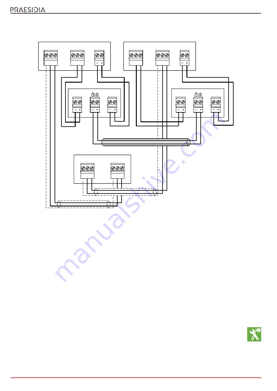
The connection of the various nodes in the network can be achieved through optic fiber using the
appropriate converters, as in the following example.
In cases where a fiber optic cable is used over long BUS lengths, it is necessary to use a RS485/fiber converter (non-INIM
brand product). The module IFMNET has a 12V output (
paragraph 3.1 - [D]
) for the power supply to the converter in use.
3.3
Supervision of the network
Once the network is configured, in the event of interruption of a single connection, each node will signal the
fault but the network will continue to function, albeit at a reduced speed.
In the event of a lost node (complete shutdown or fault on the IFMNET module) all the other nodes in the network will
signal the fault.
3.4
Commissioning of a network
Once several control panels have been connected in a network, as indicated in the diagrams shown in the
previous paragraphs, it will be necessary to work through the following points.
1.
Supply power to each node in the network.
2.
Configure the IFMNET module of each node in the cluster.
Work through the following points for each control panel:
2.1
Access the configuration menu
To access the configuration menu it is necessary to first access the programming phase of the control
panel () and then tap on the
Configure
button which appears on the screen.
Alternatively, it is possible to tap directly on the configuration status icon.
Entry of a valid access code is necessary In both cases.
2
1
Port-A
3
D-
-
D+
2
1
Port-B
3
D-
-
D+
2
1
Port-A
3
D-
-
D+
2
1
Port-B
3
D-
-
D+
2
1
12V
2
1
Port-A
3
D-
-
D+
2
1
Port-B
3
D-
-
D+
2
1
12V
12V
Rx/Tx
12V
Rx/Tx
Converter
Converter
Optic fiber


