n
Adjustments
n
Disc Brake
No brake adjustment is required.
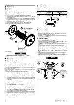
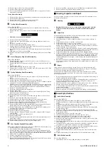
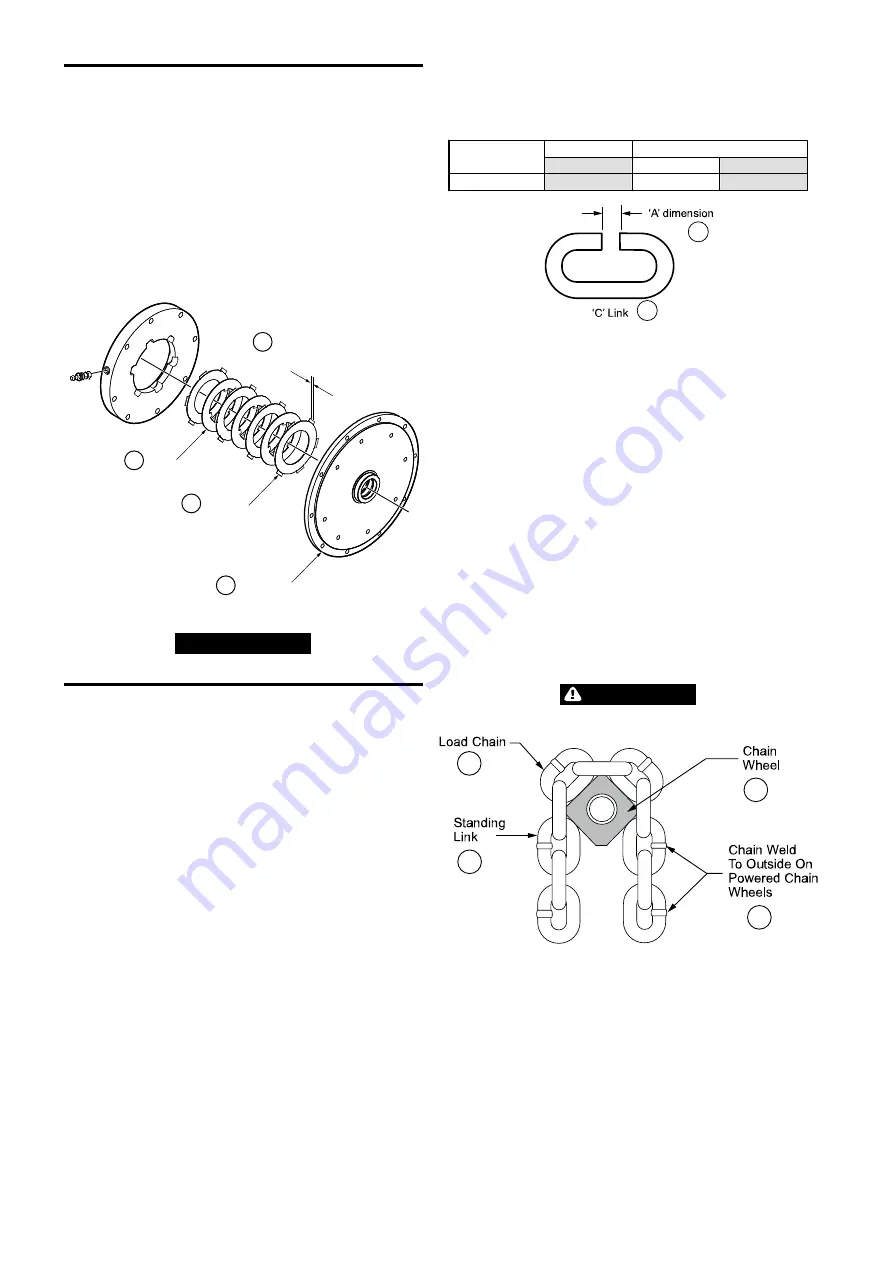
Refer to Dwg. MHP3045 on page 6,
A
. Drive Plate;
B
. Friction Plate;
C
. Reaction
Plate;
D
. 0.047 inch minimum (1.2 mm minimum).
Use the following procedure to remove the brake.
1. Remove the motor as described in ‘Hoist Motor Removal’ on page 7.
2. Remove the brake reaction plate (68), brake friction plate (66), drive plate (67)
and brake piston (63).
3. Inspect the brake friction disc (212) for wear. Friction discs (212) have 0.008 in
(0.2 mm) deep grooves on each side. Replace the friction discs (212) if grooves
are no longer visible.
4. Measure total friction disc (212) and steel disc (213) stack up. Check that
measurement is not less than 0.374 in (9.5 mm).
5. Remove, discard and replace ‘O’ rings (205) and (206) on piston (204).
No further disassembly is required, if only the brake is to be serviced.
A
B
C
D
Friction
Disc
Drive
Disc
Reaction
Plate
0.047 Inch minimum
(1.2 mm minimum)
(Dwg. MHP3045)
NOTICE
• Original brake friction plate thickness is 0.059 in (1.5 mm).
n
Disassembly
n
General Disassembly Instructions
Refer to the Product Parts Information Manual for item numbers referenced in
the ”MAINTENANCE” section.
The following instructions provide the necessary information to disassemble, inspect,
repair, and assemble the hoist. Parts drawings are provided in the Product Parts
Information Manual.
If a hoist is being completely disassembled for any reason, follow the order of the
topics as they are presented.
It is recommended that all maintenance work on the hoist be performed in a clean
dust free work area.
In the process of disassembling the hoist, observe the following:
1. Never disassemble the hoist any further than is necessary to accomplish the
needed repair. A good part can be damaged during the course of disassembly.
2. Never use excessive force when removing parts. Tapping gently around the
perimeter of a cover or housing with a soft hammer, for example, is sufficient to
break the seal.
3. Do not heat a part with a flame to free it for removal, unless the part being heated
is already worn or damaged beyond repair and no additional damage will occur
to other parts.
In general, the hoist is designed to permit easy disassembly and assembly. The
use of heat or excessive force should not be required.
4. Keep the work area as clean as practical, to prevent dirt and other foreign matter
from getting into bearings or other moving parts.
5. All seals, gaskets and ’O’ rings should be discarded once they have been removed.
New seals, gaskets and ’O’ rings should be used when assembling the hoist.
6. When grasping a part in a vise, always use leather-covered or copper-covered vise
jaws to protect the surface of the part and help prevent distortion. This is
particularly true of threaded members, machined surfaces and housings.
7. Do not remove any part which is a press fit in or on a subassembly unless the
removal of that part is necessary for repairs or replacement.
8. When removing ball bearings from shafts, it is best to use a bearing puller. When
removing bearings from housings, drive out the bearing with a sleeve slightly
smaller than the outside diameter of the bearing. The end of the sleeve or pipe
which contacts the bearing must be square. Protect bearings from dirt by keeping
them wrapped in clean cloths.
n
Load Chain Replacement
Ingersoll Rand
chain is chosen according to DIN norm 5684-Grade 80 with the correct
dimensions and tolerance to suit the load sprocket.
Table 6: ’C’ Link Dimension
Hoist Model
Chain Size
’A’ Dimension
mm
in.
mm
LCA750T
32 x 90
1.38
35
A
B
(Dwg. MHP0817)
n
Removing Load Chain
1. Support the hook assembly.
2. Disconnect the load chain end from the hook assembly.
3. Remove nuts (115), lockwashers (154), stop chain axle (491), stop chain (492)
and chain stop (490) on load chain (493).
4. Run the hoist in the lifting direction of the free chain fall until the last link is
10 inches (25 cm) from the hoist.
n
Installing Load Chain
To feed load chain through bottom hook assembly:
1. Install the ‘C’ link in the last link of the load chain extending from the hoist (A).
Connect the new load chain to the ‘C’ link. The end link must be a standing link
(perpendicular to the axle of hoist sprocket wheels).
2. Run the hoist to feed the chain through the hoist body and down to (B) on the
hook block.
3. The rotation axle of the sprocket (376) in hook block assembly must be
perpendicular to the rotation axle of hoist sprockets (152) and (157) of the hoist.
4. Introduce the last link of the load chain in the opening to hook block (C). The
first link must be put in parallel to the axle. The sprocket of bottom hook assembly
and the following standing links must have the welds turned to the outside
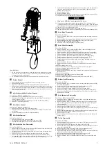
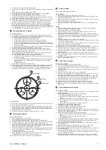
position with the sprocket. Refer to Dwg. MHP0472 on page 6,
A
. Load Chain;
B
. Chain Wheel;
C
. Chain Weld to Outside on Powered Chain Wheels;
D
. Standing
Link.
5. After exiting the hook block at (D), feed the last link of the load chain into
opening (E) of the sprocket (152) of the hoist.
6. After exiting the hoist at (F), position the last link of the load chain in the slot
(G) in the hook block assembly and attach it with axle (374), plate (263),
lockwashers (119) and capscrews (133).
WARNING
• The chain must not be twisted.
A
B
C
D
(Dwg. MHP0472)
6
Form MHD56416 Edition 1
Содержание LCA750T
Страница 13: ...SERVICE NOTES Form MHD56416 Edition 1 13 ...
Страница 14: ...SERVICE NOTES 14 Form MHD56416 Edition 1 ...
Страница 15: ...SERVICE NOTES Form MHD56416 Edition 1 15 ...
Страница 16: ...www irtools com ...


