


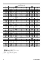


TROUBLESHOOTING
This section provides basic troubleshooting information. Determination of specific causes to problems are best identified by thorough inspections performed by
Ingersoll Rand
trained technicians. The chart below provides a brief guide to common hoist and trolley symptoms, probable causes and remedies.
SYMPTOM
CAUSE
REMEDY
Hoist will not operate.
No air supply to hoist, or too little CFM or psi. Check psi (bar) at hoist inlet. Refer to ”SPECIFICATIONS” section in Product
Information Manual for correct CFM (cu.m/min) and psi (bar).
Pendant lever sticking.
Check pendant lever and restore free movement.
Pendant malfunction.
Check psi (bar) at pendant. Minimum operating pressure in pendant line is 60
psi (4 bar).
Hoist is overloaded.
Reduce load to within rated capacity.
Motor is damaged.
Repair or replace. Refer to “MAINTENANCE” on page 5.
Limit switch sticking.
Check limit switch button moves freely. Clean and lubricate if sticking.
Brake is not releasing.
Check brake release circuit and psi (bar) at brake inlet (60 psi (4 bar) minimum).
Load continues to move when hoist is
stopped. ”UP” direction.
Pendant lever sticking.
Check lever and restore free movement.
Load continues to move when hoist is
stopped. ”DOWN” direction.
Pendant lever sticking.
Check lever and restore free movement.
Hoist is overloaded.
Reduce load to within rated capacity.
Brake is slipping.
Check brake springs and brake disc linings for wear. Refer to
“MAINTENANCE” on page 5.
Hoist will not lift rated capacity.
Hoist is overloaded.
Reduce load to within rated capacity.
No air supply to hoist or too little CFM or psi
(cu. m/min or bar).
Check psi (bar) at hoist inlet. Refer to ”SPECIFICATIONS” section in Product
Information Manual for correct CFM (cu.m/min) and psi (bar).
Brake is not releasing.
Check brake release circuit and psi (bar) at brake inlet (60 psi (4 bar) minimum).
Exhaust is restricted.
Inspect vents and clean or replace muffler.
Motor is damaged.
Check for worn motor bearings.
Hook lowers but will not raise.
Hoist is overloaded.
Reduce load to within rated capacity.
No air supply to hoist or too little CFM or psi
(cu. m/min or bar).
Check at hoist power supply connection with hoist under load. Raise pressure to
rated capacity.
Pendant malfunction.
Check psi (bar) at air inlet connection on pendant.
Load chain jumps on sprocket or is making
a snapping sound.
Worn or rusted chain.
Refer to “INSPECTION” on page 2 to determine wear limit. Replace if necessary.
Incorrect chain.
Replace with correct chain.
Worn sprocket or chain guide.
Replace worn parts.
Capsized hook.
Correct as described in “MAINTENANCE” on page 5.
Hoist not in line with load.
Align hoist with load. Do not ”yard” or ”side pull”.
Incorrectly reeved load chain.
Check load chain is correctly reeved.
No oil on load chain.
Lubricate load chain.
Trolley will not stop or trolley wheels slip. Damaged beam.
Repair or replace beam.
Excessive oil, grease or paint on track of beam. Clean off oil, grease or paint.
Trolley not spaced for beam clearance.
Check trolley spacing. Refer to the manufacturer’s literature.
Air-powered trolley does not operate.
Pendant lever sticking.
Check lever and restore free movement.
No air supply to trolley or too little CFM or psi
(cu. m/min or bar).
Check psi (bar) at trolley inlet. Refer to manufacturer’s specifications.
MAINTENANCE
WARNING
• Never perform maintenance on the hoist while it is supporting a load.
• Before performing maintenance, tag controls:
WARNING - DO NOT OPERATE EQUIPMENT BEING REPAIRED.
• Only allow Ingersoll Rand trained technicians to perform maintenance.
• After performing any maintenance on the hoist dynamically test the hoist to
100% of its rated capacity, in accordance with ASME B30.16 standards,
before returning hoist to service. Testing to more than 100% of rated
capacity is required to set overload device and may be required to comply
with standards and regulations set forth in areas outside the USA.
• Shut off air system and depressurize air lines before performing any
maintenance.
• Use of other than genuine Ingersoll Rand replacement parts may result in
safety hazards, decreased performance and increased maintenance and may
invalidate all warranties.
n
Maintenance
Personnel trained and certified by the owner/user are the only personnel authorized
to do repair or maintenance on a hoist. Correct disassembly (to prevent loss or damage
of good parts), repair, assembly, testing and adjusting are critical to proper hoist
operation. Maintenance procedures are technical in nature and require training and
experience to accomplish correctly. In addition, repair and testing require specialized
equipment that is not typically found at the hoist-mounting site.
Proper use, inspections and maintenance increase the life and usefulness of your
Ingersoll Rand
equipment. During assembly, lubricate gears, nuts, capscrews and all
machined threads with applicable lubricants. Use of antiseize compound and/or
thread lubricant on capscrew and nut threaded areas prevents corrosion and allows
for easy disassembly of components.
It is extremely important that mechanics’ and operators be familiar with the servicing
procedures of these hoists or similar products, and are physically capable of
conducting the procedures. These personnel shall have a general working knowledge
that includes:
1. Proper and safe use and application of mechanics’ common hand tools as well as
special
Ingersoll Rand
or recommended tools.
2. Safety procedures, precautions and work habits established by accepted industry
standards.
Ingersoll Rand
cannot know of, or provide all the procedures by which product
operations or repairs may be conducted and the hazards and/or results of each
method. If operation or maintenance procedures not specifically recommended by the
manufacturer are conducted, it must be ensured that product safety is not endangered
by the actions taken. If unsure of an operation or maintenance procedure or step,
personnel should place the product in a safe condition and contact supervisors and/
or the factory for technical assistance.
n
Maintenance Intervals
Refer to the ‘Maintenance Interval Chart’ on page 3 for recommended maintenance
schedule.
Form MHD56416 Edition 1
5
Содержание LCA750T
Страница 13: ...SERVICE NOTES Form MHD56416 Edition 1 13 ...
Страница 14: ...SERVICE NOTES 14 Form MHD56416 Edition 1 ...
Страница 15: ...SERVICE NOTES Form MHD56416 Edition 1 15 ...
Страница 16: ...www irtools com ...


