


10. Remove supports (111) from trolley axle (107).
11. Remove sleeves (109) from trolley axle (107).
12. Do not remove bushings (110) from trolley axle (107) or support (111) unless
replacement is required.
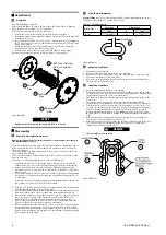
Trolley Wheel Disassembly
1. Remove retainer ring (126) and pull wheel assembly from trolley side plate axle.
2. Remove retainer ring (125).
3. Remove spacer (127), seal ring (128) and spacer (129).
4. Remove roller bearings (130) and seal ring (128).
n
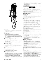
Trolley Motor Disassembly
Refer to Dwg. MHP1651.
1. Remove capscrews (333) and washers (332) to separate motor from trolley
reduction gear assembly.
2. Remove capscrews (328) in motor cover (325) and separate from motor housing
(331).
NOTICE
• Pins (309) do not have to be removed.
3. Remove and discard ‘O’ ring (336).
4. Remove capscrews (303) and separate motor housing (308) and motor cover
(325).
5. Discard ‘O’ rings (307) and (311).
6. Remove retainer rings (315) and bearings (314).
7. Remove stop (322), slide valve (318), quad rings (319) and (321), springs (317)
and slide valve (316). Discard quad rings.
8. Immobilize the motor gears with a rod between the teeth and remove locknuts
(304).
9. Slide gears out of motor housing (308).
10. Remove screw (301) and washer (302). Press bearings (305) out of motor flange
(306).
n
Motor Emergency Stop Valve Disassembly
Refer to Dwg. MHP1651.
1. Remove capscrews securing cover (363) to motor cover (325). Remove cover.
2. Remove diaphragm (364).
3. Remove capscrews (355) securing cover (352). Remove cover and discard ‘O’ ring
(353).
4. Remove spring (354).
5. Secure valve cone (365) and remove screw (358).
6. Remove valve cone (356), valve cone (365), seals (357) and washers (361). Push
spacer (359) out of motor cover.
n
Trolley Reduction Gear Disassembly
Refer to Dwg. MHP2978.
1. Remove capscrew (133) washer (119) and washer (135) from planet support
(655).
2. Remove gear (136) and key (656).
3. Remove capscrews (270) and washers (271) from flange (651).
4. Remove plugs (176) from gear housing (668). Drain oil into a suitable container
and dispose of it in an environmentally friendly manner.
5. Carefully remove four capscrews (682) and motor flange (681) from gear housing
(668). Loosen capscrews (682) half a turn at a time until spring compression is
released. Flange was assembled with Loctite® and may be difficult to remove.
6. Remove ‘O’ ring (690) and discard.
7. Remove two mufflers (680) from flange (681).
8. Remove springs (701).
9. Remove coupling (699) and sleeve (700) from shaft spindle (678) and ‘O’ ring
(698) from groove in coupling bore.
10. Remove brake discs (695) and (694).
11. Apply low pressure air to brake port in brake housing (689) to remove piston
(692).
12. Remove ‘O’ rings (691) and (693) from piston (692).
13. Remove brake housing (689) and gasket (667) from gear housing (668).
14. Remove planet support (673), bearing (685) and ring gear (686).
15. Remove retainer ring (683) and bearing (679) from shaft spindle (678).
16. Remove ring gear (670) from gear housing (668).
17. Remove retainer ring (672). Tap drive shaft (663) from bearing (671). Remove
bearing (405) from gear housing (668). Tap out bearing (665).
18. Remove bearing (685). Tap out planet pins (677). Remove two bearings (674)
and single spacer (675) from each planet gear (676).
19. Remove retainer ring (664).
20. Tap shaft (663) out of bearing (665).
21. Remove capscrews (650) and separate flange (651), ring gear (654) from gear
housing (668).
22. Tap planet support (655) from flange (651).
23. Remove bearing (130).
24. Drive pins (662) completely into planet pins (657) then tap planet pins out of
planet support (655).
25. Remove planet gears (661), thrust bearings (659) and washers (658).
26. Remove bearing (130) and oil seal (652) from flange (651).
n
Four Function Pendant Disassembly
Refer to Dwgs. MHP1577 without emergency stop or MHP1545 with emergency stop.
1. Remove fittings (327) and lifting eye (501).
2. Unscrew plugs (518). Remove springs (517) and balls (516).
3. Remove capscrews (527) and (525) and washers (526) from attachment (left)
(523). Remove attachment (left) taking care not to damage pin (529). Separate
pin (529), lever (522) and ‘O’ rings (528) from attachment (left). Discard ‘O’ rings.
4. Repeat step 3 for attachment (right) (524).
5. Remove screw (504) from levers (503).
6. Tap out pin (502) and remove levers (503).
7. Remove valve assemblies (509). Remove ‘O’ rings (511) and (505) and protector
(506) from valve assemblies. Discard ‘O’ rings.
8. Remove plug (507) or emergency stop valve (508) from pendant handle (514).
9. Remove retainer ring (512) and exhaust washer (513).
n
Cleaning, Inspection and Repair
Use the following procedures to clean, inspect, and repair the components of the
hoist and trolley system.
n
Cleaning
CAUTION
• Bearings that are loose, worn or rotate in the housing must be replaced.
Failure to observe this precaution will result in additional component
damage.
n
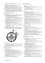
Inspection
All disassembled parts should be inspected to determine their fitness for continued
use. Pay particular attention to the following:
1. Check mufflers for damage or excessive dirt.
2. Check side plates for cracks or bending, replace if one of these conditions is
found.
3. Inspect all gears for worn, cracked or broken teeth.
4. Inspect all bushings for wear, scoring or galling.
5. Inspect all bearings for play, distorted races, pitting and roller or ball wear or
damage. Inspect bearings for freedom of rotation. Replace bearings if rotation is
rough or bearings are excessively worn.
6. Inspect shafts for ridges caused by wear. If ridges caused by wear are apparent
on shafts, replace the shaft. Inspect all surfaces on which oil seal lips seat. These
surfaces must be very smooth to prevent damage to the seal lip.
7. Inspect all threaded items and replace those having damaged threads.
8. Inspect the brake drive plates and friction discs for oil. If the friction discs have
become oil-soaked, replace them. If the drive plates have become glazed, sand
them lightly using fine emery cloth and a flat surface as backing. Inspect the
remaining brake parts for warpage or other damage, and replace damaged parts
as necessary.
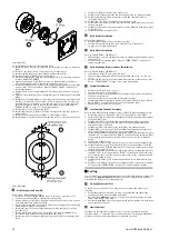
9. Measure the thickness of the brake friction disc. The brake friction disc must show
and even wear pattern. If the brake friction disc is 0.047 inches (1.2 mm) or less,
replace discs.
n
Repair
Clean all hoist component parts in solvent. The use of a stiff bristle brush will
facilitate the removal of accumulated dirt and sediments on the gears and frames.
Dry each part using low pressure, filtered compressed air.
Actual repairs are limited to the removal of small burrs and other minor surface
imperfections from gears and shafts. Use a fine stone or emery cloth for this work.
Do not use steel wool.
1. Worn or damaged parts must be replaced. Refer to the applicable Parts Listing for
specific replacement parts information.
2. Inspect all remaining parts for evidence of damage. Replace or repair any part
which is in questionable condition. The cost of the part is often minor in
comparison with the cost of redoing the job.
3. Smooth out all nicks, burrs or galled spots on the shafts, bores, pins, or bushings.
4. Examine all gear teeth carefully, and remove nicks or burrs.
5. Polish the edges of all shaft shoulders to remove small nicks which may have been
caused during handling.
6. Remove all nicks and burrs caused by lockwashers.
7. Replace all gaskets, oil seals and ‘O’ rings removed during hoist disassembly.
n
Assembly Instructions
n
Hoist Motor Assembly
Refer to Dwg. MHP2973.
1. Install bearing (408) and retainer ring (409) on motor shaft (407).
2. Install assembled motor shaft in motor flange (403) and secure with retainer ring
(410).
3. Install bearings (405) and external gears (411) in motor flange (403).
4. Install ‘O’ rings (444) and bearings (442) in motor flange (439).
5. Install motor drive gears (436) and motor idle gears (435) in motor flange (439).
Secure with nuts (443).
6. Install pins (404) in motor housings (424) if removed during disassembly.
7. Align pin holes and install motor housings (424) on motor flange (439). Secure
with capscrews (421).
8. Install bearings (419) in front end covers (422).
9. Clamp bearings (419) with washers (178) and capscrews (415).
10. Install oil seals (220) and ‘O’ rings (416) in oil seal supports (417).
11. Install assembled oil seal supports (417) in motor housing (429).
12. Align dowel pins (404) and install front end covers (422) on gear housings (424).
Secure with capscrews (421).
13. Carefully install assembled gear unit in motor housing (429) by pushing from the
motor flange side.
14. Secure gear unit to motor housing (429) with lockwashers (440) and capscrews
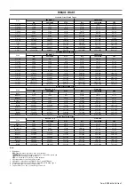
(441). Refer to ‘Torque Chart’ on page 12 for torque requirements.
15. Install ‘O’ rings (426), tubes (425) and control valve assemblies (450) on motor
housing (429) with lockwashers (440) and capscrews (555).
16. Install covers (446) with capscrews (266).
17. Install muffler brackets (428) on motor housing (429). Secure with capscrews
(427).
18. Install reducer fittings (432) and mufflers (431) in muffler brackets (428).
n
Hoist Brake Assembly
Refer to Dwg. MHP2972.
1. Lubricate and install ‘O’ rings (205) and (206) on piston (204).
8
Form MHD56416 Edition 1
Содержание LCA750T
Страница 13: ...SERVICE NOTES Form MHD56416 Edition 1 13 ...
Страница 14: ...SERVICE NOTES 14 Form MHD56416 Edition 1 ...
Страница 15: ...SERVICE NOTES Form MHD56416 Edition 1 15 ...
Страница 16: ...www irtools com ...


