A
B
C
D
E
F
G
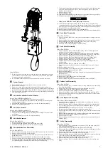
(Dwg. MHP3044)
7. On the free end of the load chain, install the chain stop (490) and stop chain
(492) with the stop chain axle (491), lockwashers (154) and nuts (this buffer
activates the bottom switch limit).
8. As a minimum attach the buffer to the 9th link from the load chain end.
n
System Removal
1. Shut off, bleed down air supply then disconnect and tag air lines.
2. Remove beam rail stops.
3. Support hoist and trolley system with adequate lifting system and remove.
4. Remove capscrews (482) and washers (481) securing chain bucket to central chain
guides (141) and (142). Refer to Dwg. MHP2977. Remove chain bucket assembly.
5. Prior to removing hoist brake, reduction gear or motor assemblies, remove hook
and load chain from hoist.
n
Hoist Brake and Reduction Gear Removal
Refer to Dwgs. MHP2971 and MHP2972.
1. Remove nuts (115), lockwashers (154) from screw rods (153).
2. Support brake and reduction gear assembly, and carefully pull assembly from
central chain guide (141).
3. Set brake and reduction gear assembly to one side for later disassembly.
4. Remove ‘O’ rings (261) and (262).
n
Hoist Motor Removal
Refer to Dwgs. MHP2971 and MHP2973.
1. Remove capscrews (406) from motor flange (403).
2. Support motor assembly (400), and carefully pull assembly from central chain
guide (142).
3. Set motor assembly to one side for later disassembly.
n
Hoist Brake Removal
Refer to Dwg. MHP2972.
1. Remove capscrews (201) from cover (202).
2. Carefully pull brake assembly (199) from brake cover (219).
3. Set brake assembly (199) to one side for later disassembly.
n
Hoist Reduction Gear Disassembly
Refer to Dwg. MHP2972.
1. Remove retainer ring (214) from pinion shaft (237) and pull out disc hub (211).
2. Remove retainer ring (216) from brake side.
3. Carefully tap on motor end of pinion shaft (237) until it can be removed from
brake cover (219).
4. Remove the ten capscrews (218) and carefully remove brake cover (219).
5. Remove ring gear (225) from reduction gear housing (241) and keys (224).
6. Using the two puller screw holes M8 provided in the planetary gear support (236),
pull planetary support assembly from reduction gear housing (241).
7. To disassemble planetary assembly, remove bearings (221), push out planet axles
(235) and remove planet gears (234), thrust rings (230), spacers (233) and
bearings (229) and (232).
8. Remove ring gear (228).
9. Remove capscrews (242).
10. Separate gear flange (260) and reduction gear housing (241) from ring gear (254).
11. Pull planetary support assembly from sun gear (238).
NOTICE
• If sun gear is difficult to move, gently tap it to loosen.
12. To disassemble planetary assembly, remove bearing (253), drive pins (243)
completely through to the inside of the planetary support (249). Push out planet
axles (244) and remove planet gears (247), thrust rings (245) and bearings (246).
13. Tap pins (243) out of planet axles (244).
14. Remove spacer (252) and retainer rings (240) and (251).
15. Tap sun gear (238) from reduction gear housing (241) and extract bearing (239).
n
Hoist Brake Disassembly
Refer to Dwg. MHP2972.
1. Remove capscrews (201) from cover (202). Separate brake assembly from brake
cover (219).
2. Remove friction disc housing (208), friction discs (212) and steel discs (213).
3. Remove brake housing (207) and brake springs (203) from cover (202).
4. Tap piston (204) from brake housing (207).
5. Remove ‘O’ rings (205) and (206) from piston (204).
n
Hoist Motor Disassembly
Refer to Dwg. MHP2973.
1. Remove capscrews (427), muffler brackets (428), reducer fittings (432) and
mufflers (431) from motor housing (429).
2. Remove capscrews (555) and lockwashers (440) from control valve assembles
(450). Remove control valve assemblies (450), tubes (425) and ‘O’ rings (426).
3. Remove capscrews (266) and covers (446) from motor flange (439).
4. Remove capscrews (441) and lockwashers (440) from motor flange (439).
5. Carefully remove the gear motor assembly from motor housing (429).
6. Remove capscrews (406) from inside of motor housing (429).
7. Carefully remove the gear unit by prying motor flange assembly from motor
housing (429).
8. Remove capscrews (421) on front end covers (422).
9. Remove front end covers (422) and motor housings (424) from motor flange
(439).
10. Remove retainer rings (412).
11. Remove assembled oil seal supports (417) from motor housing (429).
12. Remove capscrews (415) and washers (178).
13. Remove bearings (419).
14. Remove nuts (443) and ‘O’ rings (444). Extract motor drive gears (436) and motor
idle gears (435).
15. Remove bearings (442).
16. Remove motor shaft (407) from motor flange (403).
17. Remove external gears (411).
18. Remove retainer ring (409) and bearing (408) from motor shaft (407).
n
Bottom Hook Disassembly
Refer to Dwg. MHP2975.
1. Remove capscrews (133), lockwashers (119), locking plate (263) and axle (374)
from hook block (380).
2. Remove nuts (115) and lockwashers (154) from threaded rods (375).
3. Carefully pry hook block halves (380) and (381) apart.
4. Remove sprocket (376) with bearings (149) and seal rings (150).
5. Remove hook (382) or clevis (385), thrust bearing (378) and split ring (377).
6. Remove bearings (149) and seal rings (150) from sprockets only if they require
replacement or cleaning.
n
Hoist Suspension Disassembly
Refer to Dwgs. MHP2970 and MHP2971.
1. Remove load chain, limit switch assemblies (168), hoist brake and reduction
assembly and motor assembly.
2. Remove capscrews (106), lockwashers (105) and caps (113) from shafts (139).
3. Tap out shafts (139) and remove suspension assembly and spacers (137) from
trolley assemblies.
4. Remove nuts (115) and lockwashers (154) from screw rods (153).
5. Pry reduction gear flange (260) from central chain guide (141).
6. Remove capscrews (106), lockwashers (105) and caps (156) from the central chain
guide (141).
7. Remove central chain guide (141), chain guide (143) and chain guide stop (146).
8. Remove sprocket (157) with bearings (158) and (161).
9. Remove screw rods (153).
10. Remove chain guide housing (151), chain guide (144) and sprocket (152) with
bearings (149).
n
Trolley Disassembly
Refer to Dwg. MHP2970.
1. Remove capscrew (133), lockwasher (119), washer (135) and drive gear (136)
from trolley drive assembly.
2. Remove trolley drive assembly from side plates (102) and (103).
3. Remove capscrews (106), lockwashers (105) and suspension shaft caps (123) from
side plates (102) and (103).
4. Remove nuts (115) from screw rods (116). Remove screw rods (116).
5. Remove side plates (102) and (103) from supports (111).
6. Remove remaining capscrews (106), lockwashers (105) and suspension shaft caps
(123) from outside of side plates (101) and (104).
7. Note position and quantity of spacers then remove spacers (137).
8. Remove side plates (101) and (104) from supports (111).
9. Remove capscrews (114), lockwashers (105) and caps (113) from trolley axle
(107).
Form MHD56416 Edition 1
7
Содержание LCA750T
Страница 13: ...SERVICE NOTES Form MHD56416 Edition 1 13 ...
Страница 14: ...SERVICE NOTES 14 Form MHD56416 Edition 1 ...
Страница 15: ...SERVICE NOTES Form MHD56416 Edition 1 15 ...
Страница 16: ...www irtools com ...


