SECTION 9 - PARTS ORDERING
GENERAL
This publication, which contains an illustrated parts
breakdown, has been prepared as an aid in locating
those parts, which may be required in the main-
tenance of the unit. All of the compressor parts,
listed in the parts breakdown, are manufactured with
the same precision as the original equipment. For
the greatest protection always insist on genuine
Ingersoll-Rand Company parts for your compressor.
The unit covered by the manual has been custom
designed and built to satisfy our customer’s unique
specifications by the Ingersoll-Rand Onboard Power
Solutions Team.
Some of the unique, special order components may
not be included in the illustrated parts breakdown.
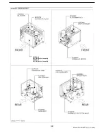
Supplemental pages with photo illustrations have
been added to assist in identifying special order
parts when required for service orders.
Contact the Onboard Power Solutions Parts
Department for assistance when ordering these
special parts. Include the unit serial number with all
orders.
NOTE: Ingersoll-Rand Company can bear no
responsibility for injury or damages resulting
directly from the use of non-approved repair
parts.
Ingersoll-Rand Company service facilities and parts
are available worldwide. There are Ingersoll-Rand
Company Construction Equipment Group Sales
Offices and authorized distributors located in the
principal cities of the United States. In Canada the
Canadian Ingersoll-Rand Company, Limited services
our customers. There are also Ingersoll-Rand
International autonomous companies and authorized
distributors located in the principal cities throughout
the free world.
Special order parts may not be included in this
manual. Contact the Mocksville Parts Department
with the unit serial number for assistance with these
special parts.
DESCRIPTION
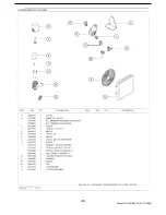
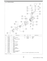
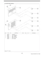
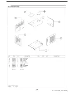
The illustrated parts break down illustrates and lists
the various assemblies, subassemblies and detailed
parts, which make up this particular machine. This
covers the standard models and the more popular
options that are available. A series of illustrations
show each part distinctly and in location relative to
the other parts in the assembly. The part number,
the description of the part and the quantity of parts
required are shown on each illustration or on
adjacent page.
The quantities specified are the number of parts
used per one assembly and are not necessarily the
total number of parts used in the machine. Where
no quantity is specified the quantity is assumed to
be one.
Each description of a part is based upon the “noun
first” method, i.e., the identifying noun or item name
is always the first part of the description. A single
descriptive modifier generally follows the noun
name. The descriptive modifier may be followed by
words or abbreviations such as upper, lower, inner,
outer, front, rear, RH, LH, etc. when they are essent-
ial.
In referring to the rear, the front or to either side of
the unit, always consider the drawbar end of the unit
as the front. Standing at the rear of the unit facing
the drawbar (front) will determine the right and left
sides.
FASTENERS
Both SAE/inch and ISO/metric hardware have been
used in the design and assembly of these units. In
the disassembly and reassembly of parts, extreme
care must be taken to avoid damaging threads by
the use of wrong fasteners. In order to clarify the
proper usage and for exact replacement parts, all
standard fasteners have been identified by part
number, size and description. This will enable a
customer to obtain fasteners locally rather than
ordering from the factory. These parts are identified
in tables that will be found at the rear of the parts
illustrations. Any fastener that has not been ident-
ified by both part number and size is a specially
engineered part that must be ordered by part
number to obtain the exact replacement part.
MARKINGS AND DECALS
NOTE: Do not paint over safety warnings or
instructional decals. If safety-warning decals be-
come illegible, immediately order replacements
from the factory.
Part numbers for original individual decals and their
mounting locations are shown within Parts List.
(
38
)
Manual P/N 22189203 (01/17/2005)
Содержание HP60CMH
Страница 6: ... 6 Manual P N 22189203 01 17 2005 ...
Страница 7: ... 7 Manual P N 22189203 01 17 2005 ...
Страница 8: ... 8 Manual P N 22189203 01 17 2005 ...
Страница 9: ... 9 Manual P N 22189203 01 17 2005 9 Manual P N 22189203 01 17 2005 ...
Страница 10: ... 10 Manual P N 22189203 01 17 2005 10 Manual P N 22189203 01 17 2005 ...
Страница 41: ... 41 Manual P N 22189203 01 17 2005 ...
Страница 42: ...22147409 90CFM Cooler Assembly 22489389 60CFM Cooler Assembly 42 Manual P N 22189203 01 17 2005 ...
Страница 43: ... 43 Manual P N 22189203 01 17 2005 ...
Страница 44: ...22173538 44 Manual P N 22189203 01 17 2005 ...
Страница 45: ...UNLOADER ASSEMBLY 45 Manual P N 22189203 01 17 2005 ...
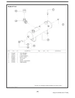
Страница 46: ...Separator Tank 46 Manual P N 22189203 01 17 2005 ...
Страница 47: ... 47 Manual P N 22189203 01 17 2005 ...
Страница 48: ... 48 Manual P N 22189203 01 17 2005 ...
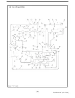
Страница 49: ...AIR OIL HYDRAULIC PIPING 49 Manual P N 22189203 01 17 2005 ...
Страница 50: ...AIR OIL HYDRAULIC PIPING 50 Manual P N 22189203 01 17 2005 ...
Страница 52: ... 52 Manual P N 22189203 01 17 2005 Wiring Diagram ...


