Compressor Discharge Piping
The customer must furnish the connection between the
compressor package and the customer air system. It is
recommended the customer use a flexible line of 3/4-inch
or larger. All piping must be certified safe for the pressures
and temperatures involved.
Wiring
The customer must connect a 12-volt supply to the
compressor to run the cooling fan, solenoid divert or valve,
and the instruments. The fan, hour meter, and discharge
temperature gage will start and stop automatically on
signal from a pressure switch internal to the compressor.
No action by the customer is required. The12-volt power
source must be capable of providing at least 27 amps
continuously. The 12-volt supply to the compressor must
be no smaller that AWG size 10 wire. Larger wire should
be used if the total wiring length exceeds 12-feet. This is
critical as the fan motor is sensitive to wiring voltage drop.
Insufficient fan speed and over heating of the compressor
will result with undersized wiring.
The compressor is protected against overheating by a
thermal-type discharge air temperature switch located in
the compressor receiver/separator. A “normally-closed”
type thermal switch, factory set at 248°F (120°C), is
supplied as standard equipment on these units. This
switch is supplied for 12-volt DC. As an option, this switch
may be supplied for 125-volt AC.
The safety shutdown function of the unit is completely
internal to the module, and operates by de-energizing the
hydraulic diverter valve to make the hydraulic flow bypass
the motor.
Regulation
The standard regulation system supplied with Ingersoll-
Rand Compressor Module units is designed to provide
capacity control for the compressor only. Variable speed
control of a driver engine is possible with additional
equipment. Consult Ingersoll-Rand Aftermarket Depart-
ment for technical assistance for these applications.
The adjustment and operation of the standard regulation
system is described in the operating instructions.
As noted therein, the unit is shipped from the factory
adjusted to 100 psig discharge pressure. The operator
may adjust for operation from 80 to175 psig.
Hydraulic Cooling Requirements
Every hydraulic system generates waste heat due to
normal mechanical (friction) and volumetric (slippage)
losses. In a typical circuit used to operate the air
compressor, losses occur in the compressor hydraulic
motor, customer’s hydraulic pump used to drive the motor,
and the piping pressure drops.
These losses can be reduced by specifying efficient (both
mechanically and volumetrically for pumps and motors)
components for the hydraulic system. The compressor
motor was chosen in great part due to high efficiency.
Using large hoses helps (-16 hoses instead of -12.)
It is usually NOT practical to operate this unit without a
hydraulic cooler. With a typical 40-gallon tank, depending
on beginning hydraulic oil temperature, testing dem-
onstrates that the unit is limited to 20 minutes of full load
operation in an eight-hour period. Tanks cool very slowly -
12 hours are generally needed for the oil to cool to within
30°F of the surrounding air temperature.
At full load, with a typical hydraulic pump, approximately
15-16 HP, or about 40,000 BTU/hr, is generated as waste
heat by the hydraulic system, and must be removed with a
suitable oil cooler. Reduction of compressor speed and/or
discharge pressure will diminish this heat load. Running
at 100 psig vs. 175 psig, for instance, decreases the heat
load by approximately 23%.
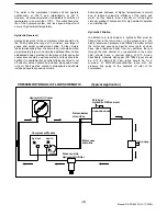
Ingersoll-Rand has available a remote oil cooler with
a12VDC electric fan that is sized for this application. This
cooler (or similar customer supplied unit) should be
installed into the return line between the compressor and
the oil tank. When specifying a cooler ensure that
pressure drop does not exceed 30 psi at 30 GPM at
operating temperature. Cooler manufacturers typically
show pressure drop plotted with viscosity. For this
application assume a viscosity range from 10cSt (59 SSU)
to 750cSt (3409 SSU), and select cooler based on 30psi
at 20cSt(100SSU.) If cooler is available with pressure
bypass, select this option and set by pass between 30 and
40 psig.
Coolers should be chosen so as to limit the hydraulic oil
temperature to 175°F in the warmest environment that the
unit will operate in. If an ambient of 100°F is anticipated,
for example, a cooler that will handle the maximum heat
load of the unit at an Entering Temperature Differential
(ETD) of 75°F would be a good choice.
The cooler selected will usually have an electric fan
included. This fan can be switched from the electrical
circuit of the compressor module unit. Connect the (+) fan
wire to terminal #7 and the (-) wire to terminal #4. The
connected fan must have a suitable fuse installed in its
wiring and must be limited to 30 amp current draw. With
this arrangement, the hydraulic oil cooler fan will switch on
and off automatically with the compressor oil cooler fan.
Hydraulic Oil Requirements
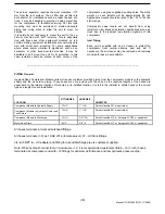
Most premium grade petroleum based hydraulic fluids can
be used with the Ingersoll-Rand Compressor Module unit.
Optimum operating viscosity is in the range of 16-40cSt
(74-185SSU). Minimum operating viscosity is 10cSt
(59SSU). Maximum operating viscosity is 750cSt (3409
SSU). Maximum cold start viscosity is 2000cSt (9240
SSU). Fluids should be chosen based on starting viscosity
at lowest anticipated oil temperature. Normally, ISO 32
grade fluids are a good choice as they are usable for
starting down to -10°F, and can operate up to about
175°F, which covers the range of hydraulic temperature
with a cooler temperature on a 100°F day. For sustained
operation in high ambient temperatures, ISO grade 46
fluid is a good choice.
(
21
)
Manual P/N 22189203 (01/17/2005)
Содержание HP60CMH
Страница 6: ... 6 Manual P N 22189203 01 17 2005 ...
Страница 7: ... 7 Manual P N 22189203 01 17 2005 ...
Страница 8: ... 8 Manual P N 22189203 01 17 2005 ...
Страница 9: ... 9 Manual P N 22189203 01 17 2005 9 Manual P N 22189203 01 17 2005 ...
Страница 10: ... 10 Manual P N 22189203 01 17 2005 10 Manual P N 22189203 01 17 2005 ...
Страница 41: ... 41 Manual P N 22189203 01 17 2005 ...
Страница 42: ...22147409 90CFM Cooler Assembly 22489389 60CFM Cooler Assembly 42 Manual P N 22189203 01 17 2005 ...
Страница 43: ... 43 Manual P N 22189203 01 17 2005 ...
Страница 44: ...22173538 44 Manual P N 22189203 01 17 2005 ...
Страница 45: ...UNLOADER ASSEMBLY 45 Manual P N 22189203 01 17 2005 ...
Страница 46: ...Separator Tank 46 Manual P N 22189203 01 17 2005 ...
Страница 47: ... 47 Manual P N 22189203 01 17 2005 ...
Страница 48: ... 48 Manual P N 22189203 01 17 2005 ...
Страница 49: ...AIR OIL HYDRAULIC PIPING 49 Manual P N 22189203 01 17 2005 ...
Страница 50: ...AIR OIL HYDRAULIC PIPING 50 Manual P N 22189203 01 17 2005 ...
Страница 52: ... 52 Manual P N 22189203 01 17 2005 Wiring Diagram ...

