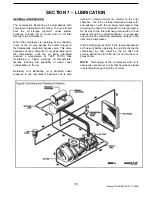
In the compressor lubricating and cooling system,
separation of the oil from the compressed air takes place
in the receiver-separator tank. As the compressed air
enters the tank, the change in velocity and direction drop
out most of the oil from the air.
Additional separation takes place in the spin-on oil
separator element, which is located on the top of the tank.
Any oil accumulation in this separator element is
continuously drained off by means of a scavenge drain
which returns the accumulated oil to the system.
SCAVENGE LINE
High-pressure air can cause serious injury or death
from hot oil and flying parts. Always relieve pressure
before removing caps, plugs, covers or other parts
from pressurized air system.
The scavenge line originates at the base of the spin-on
separator element head, and terminates at the com-
pressor airend inlet valve through an orifice/check valve.
Once a year or every 2000 hours of operation, whichever
comes first, remove this line and any orifice, thoroughly
clean, then reassemble.
NOTICE
Excessive oil carry over may be caused by an
oil logged separator element. Do not replace element
without first performing the following maintenance
procedure:
1.
Check oil level. Maintain as indicated earlier in
this section.
2.
Thoroughly clean scavenge line, orifice and
check valve.
3.
Assure minimum pressure valve is holding 80 to
90 psi.
4.
Run unit at rated operating pressure for 30 to 40
minutes to permit element to clear itself.
OIL SEPARATOR ELEMENT
The life of the oil separator element is dependent upon the
operating environment (soot, dust, etc.) and should be
replaced every twelve months or 2000 hours. To replace
the element proceed as follows:
* Ensure the tank pressure is zero.
1.
Remove roof access cover.
2.
Using strap wrench if necessary, remove spin
on separator unit by rotating counterclockwise.
NOTE: If there is any indication of formation of
varnishes, shellacs or lacquers on the oil filter
element, it is a warning the compressor lubricating oil
has improper characteristics and should be im-
mediately changed.
3.
Inspect the separator head to be sure the gasket
was removed with the oil filter element. Clean the
gasket seal area on the head.
NOTE: Installing a new separator element when the
old gasket remains on the filter head, will cause an oil
leak and can cause property damage.
4.
Lubricate the new filter gasket with the same oil
being used in the machine.
5. Install
new
separator by turning element
clockwise until gasket makes initial contact.
Tighten an additional 1/2 to 3/4 turns.
6.
Adjust oil level if necessary.
7.
Start unit and allow to build up to rated pressure.
Check for leaks before placing unit back into
service.
EXTERIOR FINISH CARE
This unit was painted and heat cured at the factory with a
high quality, thermoset polyester powder coating. The
following care will ensure the longest possible life from this
finish.
1.
If necessary to remove dust, pollen, etc. from
housing, wash with water and soap or dish-
washing liquid detergent. Do not scrub with a
rough cloth, pad, etc.
2.
If grease removal is needed, a fast evaporating
alcohol or chlorinated solvent can be used. Note:
This may cause some dulling of the paint finish.
3.
If the paint has faded or chalked, the use of a
commercial grade, non-abrasive car wax may
partially restore the color and gloss.
FIELD REPAIR TEXTURE PAINT
1.
The sheet metal should be washed and clean of
foreign material and then thoroughly dried.
2.
Clean and remove all grease and wax from the
area to be painted using Duponts 3900S Cleaner
prior to sanding.
3.
Use 320 grit sanding paper to repair any
scratches or defects necessary.
4.
Scuff sand the entire area to be painted with a
red scotch brite pad.
5.
Wipe the area clean using Duponts 3900S.
6.
Blow and tack the area to be painted.
(
30
)
Manual P/N 22189203 (01/17/2005)
Содержание HP60CMH
Страница 6: ... 6 Manual P N 22189203 01 17 2005 ...
Страница 7: ... 7 Manual P N 22189203 01 17 2005 ...
Страница 8: ... 8 Manual P N 22189203 01 17 2005 ...
Страница 9: ... 9 Manual P N 22189203 01 17 2005 9 Manual P N 22189203 01 17 2005 ...
Страница 10: ... 10 Manual P N 22189203 01 17 2005 10 Manual P N 22189203 01 17 2005 ...
Страница 41: ... 41 Manual P N 22189203 01 17 2005 ...
Страница 42: ...22147409 90CFM Cooler Assembly 22489389 60CFM Cooler Assembly 42 Manual P N 22189203 01 17 2005 ...
Страница 43: ... 43 Manual P N 22189203 01 17 2005 ...
Страница 44: ...22173538 44 Manual P N 22189203 01 17 2005 ...
Страница 45: ...UNLOADER ASSEMBLY 45 Manual P N 22189203 01 17 2005 ...
Страница 46: ...Separator Tank 46 Manual P N 22189203 01 17 2005 ...
Страница 47: ... 47 Manual P N 22189203 01 17 2005 ...
Страница 48: ... 48 Manual P N 22189203 01 17 2005 ...
Страница 49: ...AIR OIL HYDRAULIC PIPING 49 Manual P N 22189203 01 17 2005 ...
Страница 50: ...AIR OIL HYDRAULIC PIPING 50 Manual P N 22189203 01 17 2005 ...
Страница 52: ... 52 Manual P N 22189203 01 17 2005 Wiring Diagram ...

