4
INSTALLATION
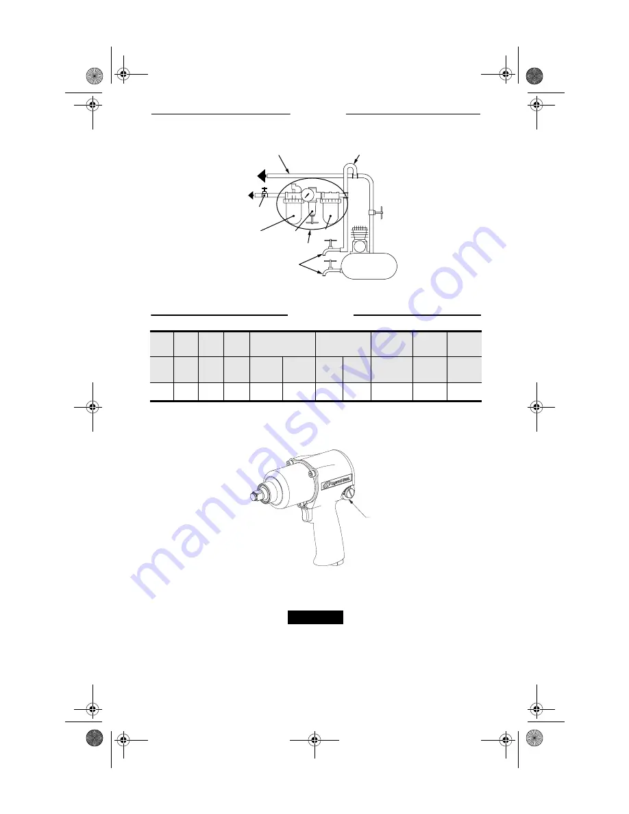
(Dwg. TPD905-2)
SPECIFICATIONS
■
Tested in accordance with PNEUROP PN8NTC1
♦
Tested to ISO8662-7
•
Tested to ISO3744
(Dwg. TPD2038)
SAVE THESE INSTRUCTIONS. DO NOT DESTROY.
When the life of the tool has expired, it is recommended that the tool be disassembled,
degreased and the parts be separated by material so that they can be recycled.
F
L
R
Main Line(s) Inner Ø
to be 3X Size of
Air Tool's Inlet Ø
To Air
System
To Air
Tool
Lubricator
Emergency
Shut-Off
Valve
Regulator
Filter
Compressor
FRL
Drain Regularly
Branch Line(s) Inner Ø
to be 2X Size of
Air Tool's Inlet Ø
Model
Handle
Drive
Impacts
/ min.
Recommended
Torque Range
■
Sound Level
dB (A)
♦
Vibrations
Level
Inlet
Connection
(Thread)
Minimum
Inside Ø
(Air Hose)
I.D.
Type
in
2
bpm
Forward
ft•lbs
(N•m)
Reverse
ft•lbs
(N•m)
Pressure
•
Power
m/s
2
NPT
in (mm)
231G
pistol
1/2” 1,200
25 to 300
(34 to 407)
25 to 350
(34 to 475)
94.5
107.5
4.7
1/4
3/8 (10)
231G
5 Letter
Date Code
location
SR __ __ __
NOTICE
P7631eng.fm Page 4 Friday, May 23, 2003 8:04 AM


