57
XtrapulsCD1-a
Chapter 8 - Appendix
12
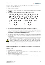
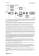
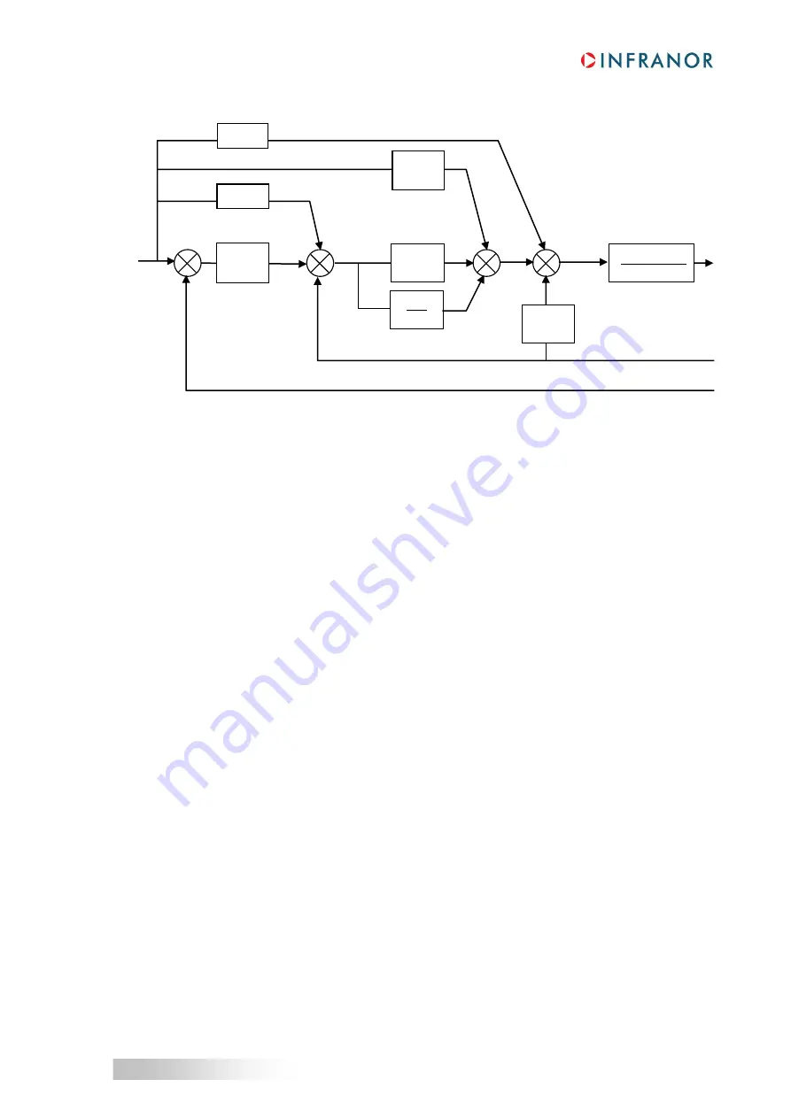
– SERVO CONTROLLER STRUCTURE
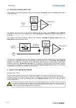
Speed error low-pass filter (Fev): defines the cut-off frequency at -3dB of the first order filter which acts on the
current command (Idc). This value is calculated by the drive during the auto tuning procedure and depends on the
selected bandwidth and the selected filter type.
Proportional speed gain (KP2): defines the proportional gain of the controller which acts on the speed error. Its
value is calculated by the drive during the auto tuning procedure. It can then be modified by the user if required.
Integral speed gain (KI): defines the integral gain of the controller which acts on the speed error. Its value is
calculated by the drive during the auto tuning procedure. It can then be modified by the user if required
Damping gain (KC): defines the proportional gain of the controller which acts only on the speed feedback. Its
value is calculated by the drive during the auto tuning procedure. It can then be modified by the user if required.
Proportional position gain (KP1): defines the proportional gain of the controller which acts on the position error. Its
value is calculated by the drive during the auto tuning procedure. It can then be modified by the user if required.
Feedforward speed 1 gain (KF1): defines the feedforward speed amplitude corresponding to the speed input
command. This term allows reducing the following error during the motor acceleration and deceleration phases. Its
value is set at 1 after the auto tuning procedure if minimum following error is required. It can then be modified by
the user if required.
Feedforward speed 2 gain (KF2): defines the feedforward speed amplitude corresponding to the viscous frictions.
This term allows reducing the viscous frictions effect during the motor acceleration and deceleration phases. The
gain value is equal to the damping gain value + the viscous friction compensation term. After the auto tuning
procedure, the feedforward speed 2 gain is set equal to the damping gain value if minimum following error is
required. The viscous friction compensation term can be calculated by measuring the current / speed ratio at
various motor speed values.
Feedforward acceleration gain (KA): defines the feedforward acceleration amplitude corresponding to the
acceleration input command. This term allows reducing the following error during the motor acceleration and
deceleration phases. Its value is calculated by the drive during the auto tuning procedure if minimum following
error is required. It can then be modified by the user if required.
The auto tuning procedure identifies the characteristics of motor and load and calculates the controller gains.
During the procedure, various choice are available to the user.
The choice of the time interval for speed measurement (speed measurement filter) allows the selection of the
speed measurement resolution value according to the position sensor resolution value: speed resolution (rpm) =
60000/ position sensor resolution / time interval (ms). The higher the time interval value, the better the resolution,
but also the lower the servo loop gains because of the increased speed measurement delay.
The choice of the anti-resonance filter is necessary in case of loud noise in the motor due to the motor/load
coupling elasticity.
The choice of the maximum stiffness filter allows a maximum stiffness on the motor shaft with regard to the torque
disturbances. However, this choice is only possible without any resonance due to the motor/load coupling
elasticity.
KA.s
2
KF1.s
KF2.s
KP2
KI
s
KC
2 .
. Fev
s+2.
. Fev
KP1
_
_
+
-
_
-
-
+
+
+
+
+
+
+
Position
reference
Idc
Speed
Position

