51
XtrapulsCD1-a
Chapter 8 - Appendix
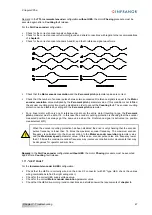
2 - ADJUSTMENT TO VARIOUS RESOLVER TYPES
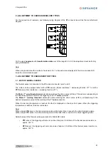
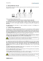
For the connection of resolvers, see following wiring diagram of the
X1
connector as well as the manufacturer's
diagram:
For the use of
resolvers
with
transformation ratios
out of the range 0.3 to 0.5, the adjustment must be factory
set by INFRANOR.
Note
When using resolvers with a number of pole pairs N > 1, all speed values displayed in the drive are equal to N
times the motor rotation speed.
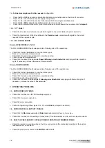
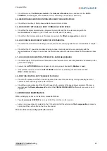
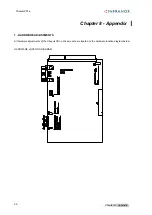
3 - ADJUSTMENT TO VARIOUS MOTOR TYPES
3.1 - MOTOR THERMAL SENSOR
The thermal sensor is connected to the
X1
resolver connector, pins 1 and 2.
The motor can be equipped either with a
CTN
sensor (Ohmic resistance = decreasing function of T°) or with a
CTP
sensor (ohmic resistance = increasing function of T°).
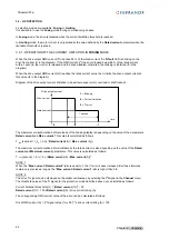
The
Motor T° error threshold
parameter allows entering the ohmic value (kOhm) of the sensor corresponding to
the desired temperature value for the triggering of the
T° motor
protection.
The
Motor T° warning threshold
parameter allows entering the ohmic value (kOhm) corresponding to the
desired temperature value for the warning of the
T° motor
protection.
When the warning temperature is reached, the fault is displayed on the drive front panel. When the triggering
temperature is reached, the drive is disabled.
Note:
When using a
CTN
sensor, the ohmic warning value will be higher than or equal to the ohmic triggering value.
When using a
CTP
sensor, the ohmic warning value will be lower than or equal to the ohmic triggering value.
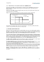
Default values of the thermal probe parameters for MAVILOR motors:
o
PTC
sensor: the triggering will occur at a value of approx. 3.3 kOhms of the thermal sensor resistor, i.e.
approx. 140°C.
o
NTC
sensor: the triggering will occur at a value of approx. 3.3 kOhms of the thermal sensor resistor, i.e.
approx. 140°C.


